Product description
Dimensions
BNI XG1-505-0A5-R067 / BNI XG3-302-0B5-R067
BNI XG3-508-0B5-R067 / BNI XG5-508-0B5-P067
BNI XG5-508-0B5-R067 / BNI XG5-538-0B5-R067

Dimensions BNI XG1-505-0A5-R067 / BNI-XG3-302-0B5-R067 / BNI-XG3-508-0B5-R067 / BNI XG5-508-0B5-R067 / BNI XG5-538-0B5-R067
BNI XG3-302-1B5-Z067 /
BNI XG5-508-1B5-Z067 / BNI XG5-538-1B5-Z067

Dimensions BNI XG3-302-1B5-Z067 / BNI XG5-508-1B5-Z067 / BNI XG5-538-1B5-Z067
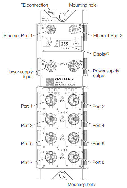
Construction
Note
Only for BNI XG5-…-1B5-… _variants.
Function
The IO-Link multiprotocol master is a decentralized and configurable gateway that processes and evaluates the input and output signals of standard sensors and actuators as well as process data from connected IO-Link devices.
The data is transmitted via an existing fieldbus interface to a higher-level controller set up by the user for further processing.
A web server is available on the IO-Link master for configuration and diagnostics.
Note
For configuration information, see the configuration guide at www.balluff.com on the product page.
Variant |
I/O-Port |
IO-Link Port |
|
|---|---|---|---|
- |
- |
Class A |
Class B |
BNI XG1-505-0A5-R067 |
- |
1…8 |
– |
BNI XG3-302-0B5-R067 |
1…8 |
– |
– |
BNI XG3-302-1B5-Z067 |
1…8 |
– |
– |
BNI XG3-508-0B5-R067 |
– |
1…8 |
– |
BNI XG5-508-0B5-P067 |
– |
1…8 |
– |
BNI XG5-508-0B5-R067 |
– |
1…8 |
– |
BNI XG5-538-0B5-R067 |
– |
1…4 |
5…8 |
BNI XG5-508-1B5-Z067 |
– |
1…8 |
– |
BNI XG5-538-1B5-Z067 |
– |
1…4 |
5…8 |
Note
Please check whether IO-Link is supported by your module before using this function. For more information on product variants that support IO-Link, see Supported product variants
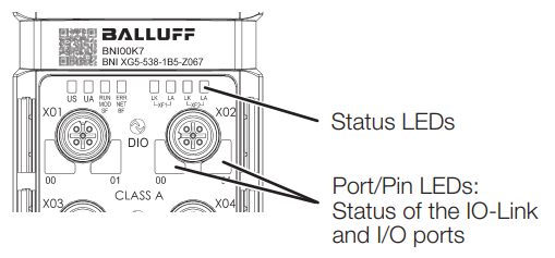
Display elements
Note
For flashing behavior in autodetect mode, see Startup.
Status LEDs
Note
Specified voltage level according to DIN EN 61131.
Power supply
LED |
Signal |
Meaning |
|---|---|---|
US |
Green, static |
Input voltage OK |
Red flashing |
Input voltage too low (< ~20.5 V DC) |
|
UA |
Green, static |
Output voltage OK |
Red flashing |
Output voltage too low (< ~20.5 V DC) or too high (> ~28.7 V DC) |
|
Red, static |
No output voltage present (< ~10.4 V DC) |
Profinet communication
LED |
Signal |
Meaning |
|---|---|---|
SF |
Off |
No error |
Red, static |
Watchdog timeout; channel, general or extended diagnostics present; system error |
|
Red flashing |
DCP signal service started via bus. |
|
BF |
Off |
No error |
Red, static |
Low speed of physical link; or no physical link |
|
Red flashing |
No data exchange or no configuration |
Ethernet/IP communication
LED |
Signal |
Meaning |
|---|---|---|
MOD |
Green flashing |
Incorrect or no module configuration |
Green, static |
Module in progress. |
|
Red flashing |
Fixed bus cycle not possible |
|
Red-Green |
Starting sequence |
|
NET |
Off |
Module has no IP address. |
Green flashing |
Module has an IP address, but |
|
Green, static |
Connection is established. |
|
Red flashing |
Connection timeout |
|
Red-Green |
Starting sequence |
EtherCAT communication
LED |
Signal |
Meaning |
|---|---|---|
RUN |
Off |
Device is in INIT state. |
Green flashing |
Device is in PRE-OPERATIONAL state. |
|
Green slowly flashing |
Device is in SAFE-OPERATIONAL state. |
|
Green, static |
Device is in OPERATIONAL state. |
|
ERR |
Off |
No errors |
Red flashing |
Invalid configuration |
|
Red slowly flashing |
Local error |
|
Red, fast flashing |
Application watchdog timeout |
|
Red, static |
Error in application |
Modbus TCP communication
LED |
Signal |
Meaning |
|---|---|---|
RUN |
Green slowly flashing |
Module is ready to establish a connection. |
Green, static |
Connection is established. |
|
Yellow, fast flashing |
Existing connection has been lost. |
Ethernet Ports
LED |
Signal |
Meaning |
|---|---|---|
LA |
Off |
No data transfer and data reception |
Green, flashing |
Send and receive data with connected device. |
|
LK |
Off |
Ethernet connection is not yet established. |
Green, static |
Ethernet connection established with another device. |
Port/Pin LEDs
LED number |
Assignment |
|---|---|
LED 0 |
Pin 4 |
LED 1 |
Pin 2 |
Port/Pin LEDs Standard Port
Signal |
Meaning |
|---|---|
Off |
State of input or output pins is 0 |
Yellow, static |
State of input or output pins is 1 |
Both LEDs red flashing |
Short circuit of sensor supply between pin 1 and pin 3 |
Red, static |
Short circuit at output on pin 2/4 against pin 3 |
Red, static |
No high signal at diagnostic input |
Red, static |
24 V input signal on configured output (actuator warning) |
Port/Pin LEDs IO-Link Port
Signal |
Meaning |
|---|---|
Green, static |
IO-Link connection active |
Green flashing |
No IO-Link connection or incorrect IO-Link device |
Green, fast flashing |
IO-Link: Preoperate during data storage |
Red, fast flashing |
Validation failed / incorrect configuration of the IO-Link data length |
Red, fast flashing |
Data storage failed / incorrect device for data storage |
Red, static |
IO-Link: Short circuit of pin 4 against pin 3 |
Labeling
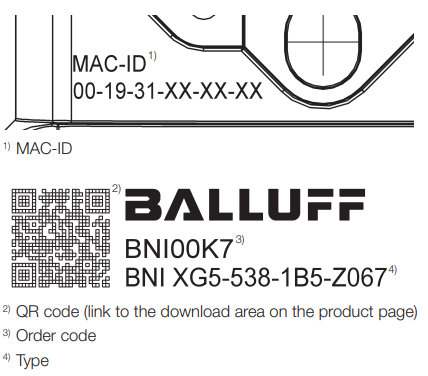
Note
Only for BNI XG…-…-Z067 _variants.

Note
Only for BNI XG…-…-R067 _variants.
Symbol on product

Warning
General warning sign ► Observe the additional approval-related and safety-related information in the product documentation.