Installation
Preparation for Installation#
Prepare installation site:
- Clean the area and check the environment for sources of interference.
- Choose a suitable position for the sensor that ensures optimal coverage.
- Select the installation site so that a sufficient distance to workplaces where people are present is maintained (see Safety instructions).
- Securely fasten the mounting bracket at the desired position.
- Plan the safe and tidy routing of cables.
Installation and Safety Instructions#
Safety Notice
High-frequency electromagnetic waves
The antenna of the radar sensor emits high-frequency electromagnetic waves.
To avoid health hazards, additional measures should be taken.
- Position the antenna so that a safety distance of at least 20 cm between the antenna and workplaces is ensured.
- Ensure that people do not stay in the immediate vicinity of the antenna for extended periods.
Effect of radiation on humans
The radiation of the wavelength emitted by the radar sensor has no known effects on the human body, apart from heat absorption in the range of a few tenths of a degree. The radiation of the radar sensor is comparable to, for example, smartphones and Wi-Fi routers, which operate in a similar frequency range. However, the transmission power of the radar sensor is much lower.
Dimensions#

Mounting the Sensor#
- Attach the sensor to the bracket and align it so that there are no foreign objects in the detection area.
- Note the blind zone of approx. 300 mm (depending on the target object and environmental conditions), in which no accurate object detection can take place. Objects in this zone can cause false reflections.
- Thin materials with low absorption, such as plastic or glass, can be placed and penetrated in the blind zone, e.g., to protect the sensor against mechanical influences. This must be tested individually.
- The maximum tightening torque of the clamping nuts when fastening the sensor is 40 Nm.
Aligning the Sensor#
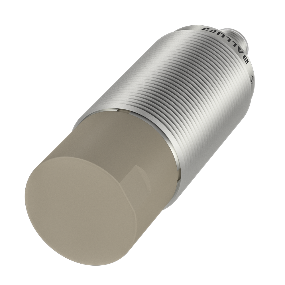
The direction of emission of the radar wave is crucial for reflection on an object. In the factory setting, the radar sensor detects the nearest object. Parameterization options can be used to specify which object should be referenced preferentially. The radar wave propagates perpendicular to the radar lens surface. The beam angle of the radar lobe is ±5°. The sensor provides the best measurement result when the marking on the cap points upwards (indicating the orientation of the radar chip).
Safety Notice
Safety notice: If the sensor is operated outdoors (without shielding above), the orientation must not exceed 0° elevation.
Notes
- For optimal performance in stationary applications, good alignment and mounting are required.
- Temperature fluctuations affect signal quality. It is recommended to acclimatize the powered sensor in the operating environment for about 15 minutes before use.
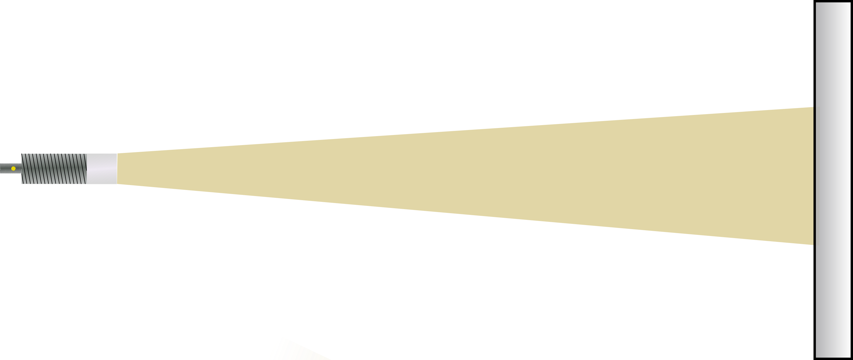
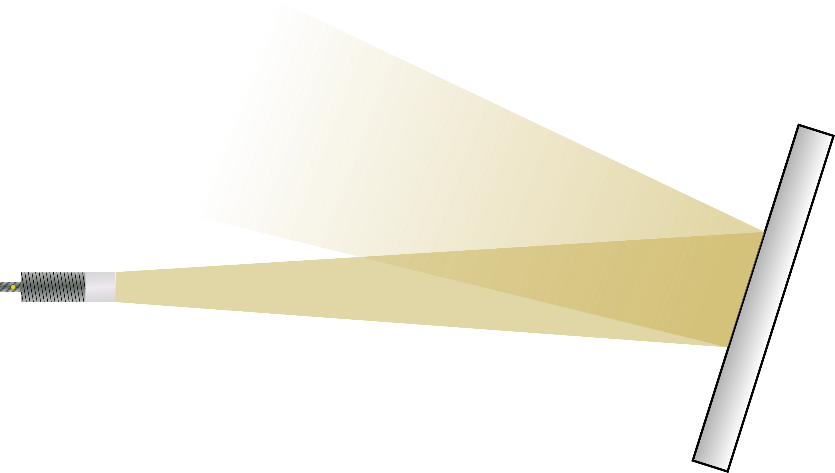
Reference objects with planar surfaces reflect the signal most strongly when the radar wave strikes at a right angle. For inclined surfaces, the angle of inclination must be less than the beam angle of the sensor to avoid false reflections.
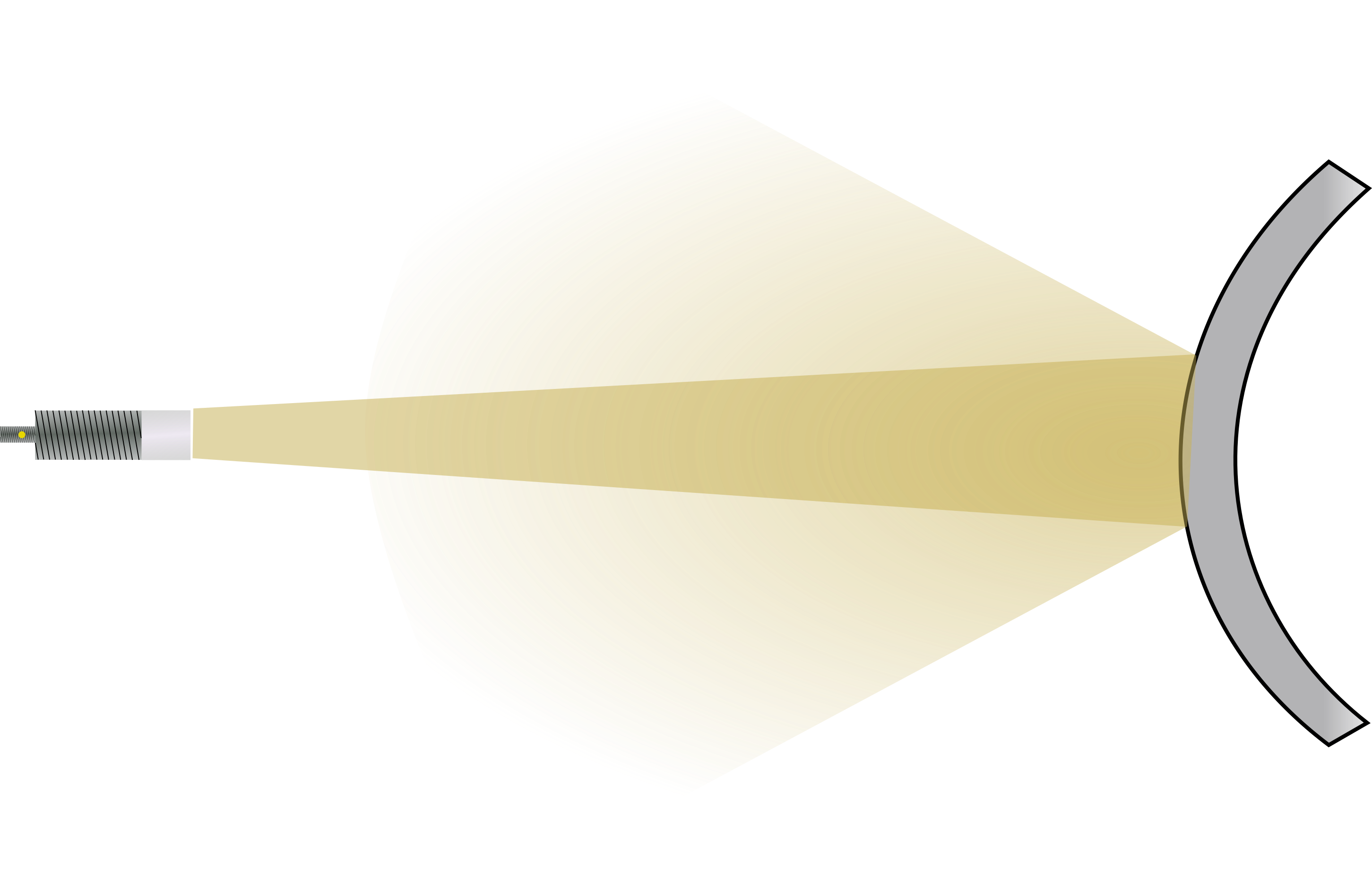
For reference objects with curved surfaces, such as cylindrical objects, align the radar sensor centrally to the reflection object. The radar signal is scattered in various directions. Although distances to such objects can be measured, the signal strength is lower than for planar surfaces.
Electrical Connection#
| IO-Link port (M12, A-coded, socket) | |||||||||||
|---|---|---|---|---|---|---|---|---|---|---|---|

|
1) Pin 2 is a configurable digital output on which various signals or functions can be output.
|
||||||||||
Connect the data cable to the IO-Link master (connection cable and accessories see www.balluff.com on the product page).
Shielding and Cable Routing#
Both unshielded and shielded cables can be used to connect the devices.
In systems with strong electromagnetic interference, the use of shielded cables is recommended. Route cables with strain relief.
Additionally, grounding the radar sensor can minimize the influence of electromagnetic interference.