Installation
Preparing for installation
Installation information
Two mounting options are provided:
Mounting in a hole with internal thread (mounting hole).
Mounting in a through-hole (without internal thread) using a mounting nut (see Accessories).
Installation guidelines
- Installation in non-magnetizable material
We recommend using non-magnetizable material to mount the BTL and magnet.
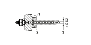
min. Ø D2 = Minimum bore diameter (see Table Bore Diameter)
No.
Description
1
Non-magnetizable material
2
Magnet
- Installation in magnetizable material
If using magnetizable material, the BTL must be protected against magnetic interference through suitable measures (e.g. spacer ring made of non-magnetizable material, a suitable distance from strong external magnetic fields).
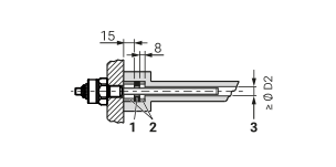
min. Ø D2 = Minimum bore diameter (see Table Bore Diameter)
No.
Description
1
Magnet
2
Spacer ring made of non-magnetizable material
Installation instructions
- Hydraulic cylinder
If installed in a hydraulic cylinder, the magnet should not make contact with the rod. Minimum bore diameter in the support piston:
Rod diameter
Bore diameter D2
10,2 mm
At least 13 mm
- Mounting hole
Depending on the version, the BTL comes with an M18×1.5 thread (according to ISO) or a 3/4“-16UNF thread (according to SAE) to secure it. Accordingly, the mounting must be made before assembly.
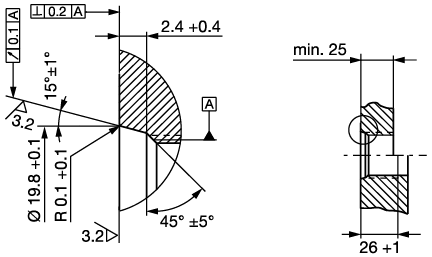
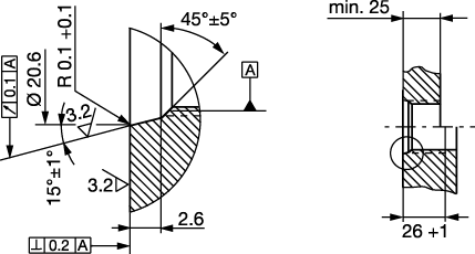
Mounting hole 3/4”-16UNF according to SAE J475 O-Ring 15.3×2.4
- Horizontal mounting
For horizontal mounting with measuring lengths > 500 mm, support the rod and, if necessary, screw it on at the end (with threaded rod end).
- Magnet
Various magnets are available for the BTL (see Accessories).
- Installation recommendation for hydraulic cylinders
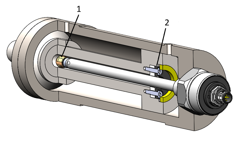
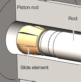
If installing horizontally in a hydraulic cylinder (measuring lengths > 500 mm), we recommend affixing a slide element to protect the rod end from wear.
Note
Dimensioning of the detailed solutions is the responsibility of the cylinder manufacturer.
The slide element material must be suitable for the appropriate load case, medium used, and application temperatures. E.g. Torlon, Teflon or bronze are all possible materials.
The slide element can be screwed on or bonded.
Secure the screws so they cannot be loosened or lost.
Select a suitable adhesive.
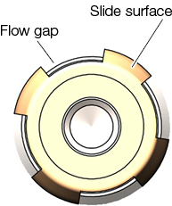
There must be a gap between the slide element and piston bore that is sufficiently large for the hydraulic oil to flow through.
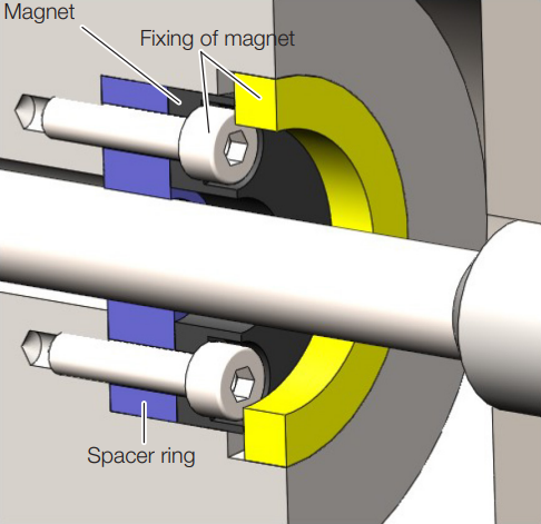
Options for fixing the magnet:
Screws
Threaded ring
Press fitting
Notches (center punching)
Note
If installed in a hydraulic cylinder, the magnet should not make contact with the rod.
The hole in the spacer ring must ensure optimum guidance of the rod by the slide element.
Installation
Note
For dimensions, see structure diagram.
Note
Suitable nuts for the mounting thread are available as accessories (see Accessories).
Notice
Interference in function
Improper installation can compromise the function of the BTL and result in increased wear.
Ensure that the contact surface of the BTL is in full contact with the mounting surface.
Seal the hole perfectly (O-ring/flat seal).
Mounting in a hole with internal thread (mounting hole)
To mount the BTL in a hole with internal thread, proceed as follows:
Make a mounting hole with thread (possibly with countersink for the O-ring) acc. to Mounting hole figure 1 or Mounting hole figure 2.
Screw the BTL with mounting thread into the mounting hole (max. torque 75 Nm).
Mounting in a through-hole
Note
Mounting in a through-hole is only permitted under ambient atmospheric pressure.
To mount the BTL in a through-hole, proceed as follows:
Guide the BTL through the hole.
Screw the mounting nut (max. torque 75 Nm, see Accessories) onto the mounting thread on the rod side.
Further steps
Install the magnet (accessory).
From measuring length of 500 mm: Support the rod and if necessary screw on at the end.
Electrical Connection
The electrical connection is made via a plug connection (for pin assignment see S92 connector) .
Note
See the information about Shielding and cable routing here.
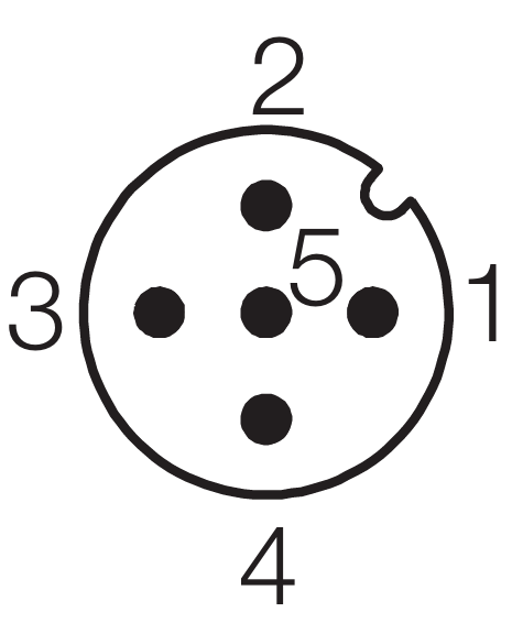
Pin |
…-E11AA… |
…-E11A1… |
…-E11AE… |
…-E11A5… |
|---|---|---|---|---|
1 |
19,2…28,8 V |
|||
2 |
0…10 V |
10…0 V |
4…20 mA |
20…4 mA |
3 |
GND[1] |
|||
4 |
0V |
|||
5 |
Unassigned[2] |
|||
Shielding and cable routing
Note
Defined ground!
The BTL and the control cabinet must be at the same ground potential.
Shielding
Observe the following instructions to ensure electromagnetic compatibility (EMC):
A shielded cable between BTL and controller can be used to increase EMC in the application. Shielding: Braided copper shield with minimum 85% coverage.
Magnetic fields
The position measuring system is a magnetostrictive system. Ensure that there is sufficient distance between the BTL and the transducer/holding cylinder and strong, external magnetic fields.
Cable routing
All cables between BTL, control and power supply must be routed tension-free. To prevent electromagnetic interference, ensure sufficient distance from high-current cables and cables carrying high-frequency voltage signals (e.g. from frequency converters).
Note
Only approved cables with a minimum cross-sectional area of AWG 24 may be used. All connected cables must have a temperature resistance of at least 85 °C. Use copper conductor, only.
Cable length
The maximum cable length is 30 m.[3]