Advanced configuration
This chapter describes various additional features of the EtherCAT Slave. Besides the function description, step-by-step guides on how to configure those features are also included.
Configuring Station Alias
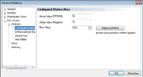
The Station Alias can be selected under the EtherCAT tab, Advanced Settings.
Note
The new value is only valid after a reset.
Ethernet over EtherCAT (EoE)
EtherCAT does not transfer any IP packets in normal operation. If IT protocols like MQTT, REST API and OPC UA shall be available when the Network Module is configured to EtherCAT, Ethernet over EtherCAT (EoE) needs to be enabled.
After the successful configuration of EoE the EtherCAT frames will tunnel Ethernet in the EtherCAT protocol thus making it possible to use the IT protocols and WebUI.
Set up
In order to be able to access the web server of the BNI module, access via EoE (Ethernet over EtherCAT) must be configured first.
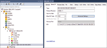
Select the Advanced Settings… button.
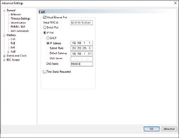
Enter valid DNS name and valid IP address.
Preparing network
Before the WebUI or any IT protocols can be reached via EoE, the network of the Beckhoff control must be configured.
Configuring Beckhoff control
A static IP address must be assigned to both network cards.
On the Beckhoff control select Start > Control Panel > Network and dial-up connections > PCI…Settings.
Assign IP address.

Under Start > Control Panel > Beckhoff CX Configuration Tool > Miscellaneous activate the setting IP Routing.

EoE and PC networks
For the EoE settings in TwinCAT, the IP address of the second network card of the Beckhoff control must be entered as a default gateway.
As a default gateway for the network configuration of the PC, the IP address of the first network card of the Beckhoff control must be entered.
File over EtherCAT (FoE)
File over EtherCAT (FoE) allows transferring files through the EtherCAT protocol to the EtherCAT slave.
The Network Modules use this mechanism to update the device firmware.
Download Firmware File/ Carry out a firmware update
Warning
During active download and installation of the firmware update a continuous power supply needs to be ensured. If power is cut during a firmware update it could damage the device and make it unusable.
For a successful firmware update, the device first needs to be put into Bootstrap state.
Open the Online tab by selecting it.
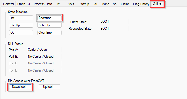
Bring the device into Bootstrap state by clicking the button.
⇒ Current State and Requested State show BOOT
Note
Bootstrap state can only be switched to if the device is in Init state. Also if the device shall be put into operation mode again it first needs to be switched back into Init.
Select Download in File Access over EtherCAT
Navigate to the folder which holds the firmware file you want to download to the device.
In the extension selection select *.*
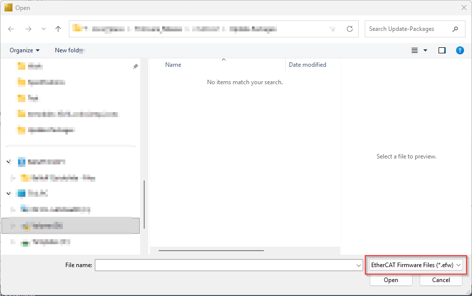
⇒ The firmware file with extension .bff should now be selectable in the dialog.
Select the desired firmware file and click Open.
In the Edit FoE Filename Dialog no changes are needed. FoE does not require a password. Click on Ok
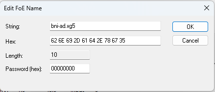
The firmware will now be downloaded to the device. A running light on the ports indicates the active download and installation. After successful download the device will automatically reboot and boot with the new firmware. Through the CoE object Firmware Build Information the current running version can be inspected and checked if the update was successful.
IO-Link Device parameterization
Connected IO-Link devices can be parameterized in two ways via EtherCAT.
CAN over EtherCAT (CoE)
Via the object 0x4000 (ISDU read/write Ch. X), IO-Link ISDU parameters can
be read from or written to the IO-Link device. For this purpose, the corresponding
index and subindex must be entered and for writing the corresponding length and
data must be entered. The read or write operation is started via the control
object. The result is displayed in the status object.
Values for the control
Value |
Function |
|---|---|
|
No function |
|
Write |
|
Read |
Values for the status
Value |
Status |
|---|---|
|
No status |
|
Active/Busy |
|
Access |
|
Error |
|
Fail |
Example of CoE setting
This example shows how the index 0x40 of Smartlight (mode) is changed by reading and writing.
Select module.
Open CoE - Online.
Activate the setting Auto Update.
Under Advanced select the setting Online - via SDO Information.
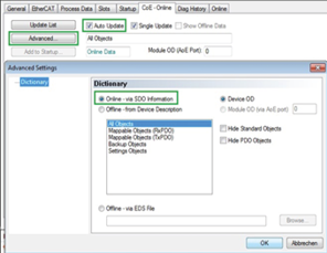
In port, select 4030:0(here channel 4).
Read index by double clicking 4030:3 and specifying the respective ISDU Index (here 0x0040).
In control write the command 0x03.
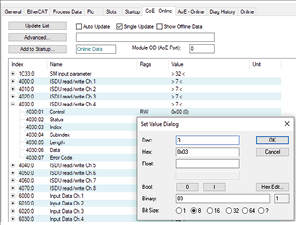
⇒ Content of the index is read and displayed in data.
Change data, specify length and use the command
0x02.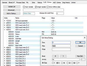
⇒ The data is written and the parameter is changed in the device.
ADS over EtherCAT Acyclic (AoE)
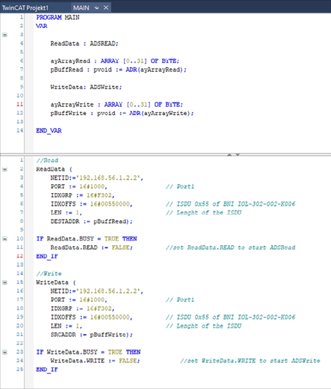
The ETG.5001.6220 describes AoE instead of CoE for the ISDU read/write access to IO-Link device parameters. Details on ADS can be found in the Beckhoff TwinCAT documentation and in ETG.1020. In contrast to CoE, AoE permits non-blocking processing.
AoE ISDU access uses these definitions (all are 32 bit):
AoE IndexGroup =
0x0000F302AoE PortNumber =
0x00001000+ IO-Link port number, starting with 0.AoE IndexOffset
16 Bit IO-Link Index
8 Bit always zero
8 Bit IO-Link Subindex
Return error code
16 Bit additional information about the error code, which is 0x0700 (ADS device error).
16 Bit error code via IO-Link
Function blocks ADSREAD and ADSWRITE
Function block ADSREAD in TwinCAT
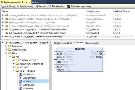
ADSREAD commands
Name |
Type |
Inherited from |
Address |
Initial |
Comment |
|---|---|---|---|---|---|
NETID |
T_AmsNetId |
– |
– |
– |
AMS NetId |
PORT |
T_AmsPort |
– |
– |
– |
ADS communication port |
IDXGRP |
UDINT |
– |
– |
– |
Index group |
IDXOFFS |
UDINT |
– |
– |
– |
IndexOffset |
LEN |
UDINT |
– |
– |
– |
Maximum number of the data bytes to be read (LEN ≤ maximum size of target buffer) |
DESTADDR |
PVOID |
– |
– |
– |
Pointer to target buffer |
READ |
BOOL |
– |
– |
– |
Rising edge starts command execution. |
TMOUT |
TIME |
– |
– |
DEFAULT_ADS_TIMEOUT |
Maximum permissible time for the execution of this ADS command |
BUSY |
BOOL |
– |
– |
– |
Busy-Flag |
ERR |
BOOL |
– |
– |
– |
Error-Flag |
ERRID |
UDINT |
– |
– |
– |
ADS error code |
Function block ADSWRITE in TwinCAT
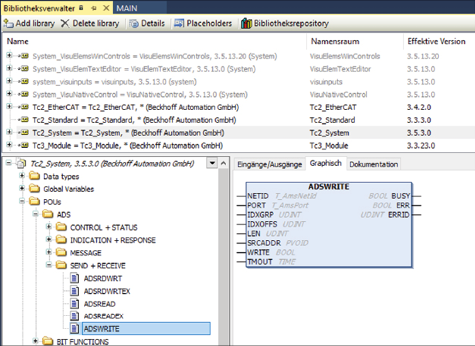
ADSWRITE commands
Name |
Type |
Inherited from |
Address |
Initial |
Comment |
|---|---|---|---|---|---|
NETID |
T_AmsNetId |
– |
– |
– |
AMS NetId |
PORT |
T_AmsPort |
– |
– |
– |
ADS communication port |
IDXGRP |
UDINT |
– |
– |
– |
Index group |
IDXOFFS |
UDINT |
– |
– |
– |
IndexOffset |
LEN |
UDINT |
– |
– |
– |
Maximum number of the data bytes to be written (LEN ≤ maximum size of source buffer) |
SRCADDR |
PVOID |
– |
– |
– |
Pointer to source buffer |
WRITE |
BOOL |
– |
– |
– |
Rising edge starts command execution. |
TMOUT |
TIME |
– |
– |
DEFAULT_ADS_TIMEOUT |
Maximum permissible time for the execution of this ADS command |
BUSY |
BOOL |
– |
– |
– |
Busy-Flag |
ERR |
BOOL |
– |
– |
– |
Error-Flag |
ERRID |
UDINT |
– |
– |
– |
ADS error code |