EtherCAT configuration
With the EtherCAT integration, the system is made up of the following components:
Bus master
Bus modules/slaves (here the bus module BNI)
Configuration
Note
Please check whether IO-Link is supported by your module before using this function. For more information on product variants that support IO-Link, see Supported product variants
During the project planning the BNI bus module is displayed as a modular device. The device data required for the project planning is stored in the ESI files. The data modules of the inputs/outputs, the IO-Link Port and any additional modules are shown in the project planning software in relation to the slot.
The ESI files make available the possible data modules (inputs/outputs, IO-Link Ports of varying data width and other additional modules).
The appropriate data modules are assigned to a certain slot for the configuration of the BNI.
After automatic scanning or manual adding of the device, the device appears in the tree structure of TwinCAT.
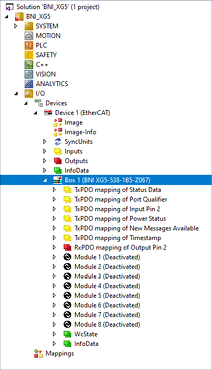
Configuring the ports
Note
Please check whether IO-Link is supported by your module before using this function. For more information on product variants that support IO-Link, see Supported product variants
The BNI is a modular EtherCAT device. It features 8 modular slots which can be configured to a specific functionality (see EtherCAT Device Basics). The configuration of the slots is done in the project planning software. The configuration is transferred to the device during the transfer of the configuration.
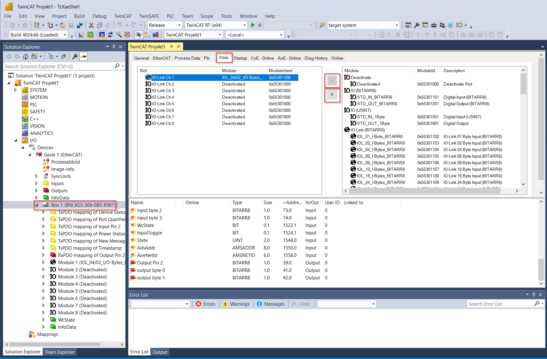
In order to configure the IO-Link Ports, a defined number of process data (buffer size) must be assigned to the EtherCAT slots. In the TwinCAT System Manager this works as follows:
Delete assignment of IO-Link channel (or port) with x.
Place the channel selected on the left side with
<the module configuration selected on the right.Transfer configuration to the EtherCAT slave with a restart of TwinCAT in Config mode.
This will assign the selected function to Pin 4 of the port. The IQ (Pin 2) functions are configured by the startup parameters.
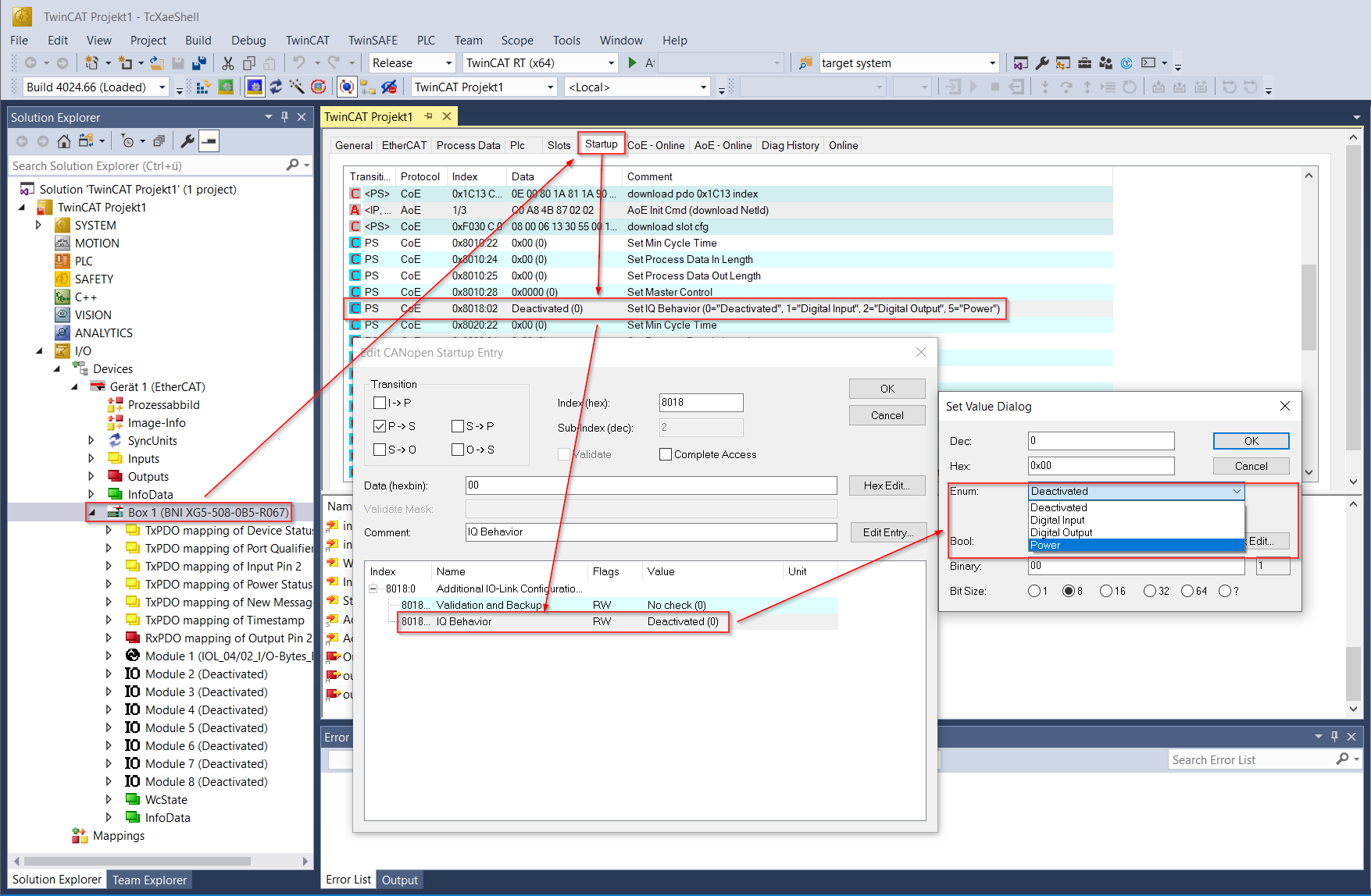
Click open the EtherCAT device in the tree structure.
Switch to the Startup tab.
Double click on the Startup Parameter entry.
In the new Dialog double click on IQ Behavior.
From the Dropdown select the desired function for Pin 2.
Save the configuration by clicking OK.
In the Startup List the selected function will now be visible in the Data column. Repeat those steps for each port of the device you want to configure.
Note
If the slot configuration is changed and another module is placed in the slot, this configuration will be lost.
Available Modules
Each port of the device can be configured to a specific functionality. For the Pin 4 configuration the following modules are available:
Deactivated
Digital Input
Digital Output
IO-Link
Modules are available in three different datatypes:
USINT (all modules)
BITARR8 (all modules)
BOOL (some IO-Link modules)
Both datatypes function the same way and only differ in the representation of the data in the engineering tool. The USINT datatype is represented as a single byte, while the BITARR8 datatype is represented as an array of 8 bits. Some of the IO-Link modules are also available with datatype BOOL for an even broader compatibility with engineering tools. It is up to the user to decide which datatype is more suitable for the application.
Deactivated Module
If the module Deactivated is selected, the corresponding Pin 4 is not used/deactivated. No process data is reserved for this Pin.
Digital Input or Digital Output Modules
Digital input and digital output modules each use 1 byte of process data.
If the port is configured as a digital input, only bit 0 of the input byte is used: 1 means the input is high, and 0 means the input is low. The remaining bits are not used.
If the port is configured as a digital output, the user can write to all 8 bits of the output byte. If at least one bit is set to 1, the output is high. The output is low only when all bits are 0.
IO-Link Modules
Note
Please check whether IO-Link is supported by your module before using this function. For more information on product variants that support IO-Link, see Supported product variants
If an IO-Link module is selected, the corresponding port is configured as an IO-Link port.
Naming of IO-Link Modules
All module names follow a naming convention that encodes process data direction, length, and data type.
Naming pattern (byte-based)
Input only
Name:IO-Link <in> Byte Input (<datatype>)
Type:IOL_<in>_I-Byte_<datatype>Output only
Name:IO-Link <out> Byte Output (<datatype>)
Type:IOL_<out>_O-Byte_<datatype>Input and output
Name:IO-Link <in> Byte Input - <out> Byte Output (<datatype>)
Type:IOL_<in>/<out>_I/O-Bytes_<datatype>
Where:
<in>/<out>= process data length in bytes<datatype>=USINTorBITARR8
Naming pattern (bit-based, BOOL)
Input only
Name:IO-Link <in> BIT Input (BOOL)
Type:IOL_<in>_I-BIT_BOOLOutput only
Name:IO-Link <out> BIT Output (BOOL)
Type:IOL_<out>_O-BIT_BOOLInput and output
Name:IO-Link <in> BIT Input - <out> BIT Output (BOOL)
Type:IOL_<in>/<out>_I/O-BIT_BOOL
Where:
<in>/<out>= process data length in bits
Note
Not all process data lengths are available as BOOL modules.
Validation and Backup
Note
Please check whether IO-Link is supported by your module before using this function. For more information on product variants that support IO-Link, see Supported product variants
Validation of the connected IO-Link device and backup of its parameter data in the network module’s parameter server are configured together via a single setting: subindex 0x01 (Validation and Backup) of the Additional IO-Link Configuration Data Ch. x object. See Additional IO-Link Configuration Data Ch. x (IO-Link variants) for the object details and the full list of values.
For enabling, the objects need to be added to the Startup Parameter List.
For this, the corresponding objects must be added.
Add all subindices to the list by clicking the New… button and selecting them from the list.
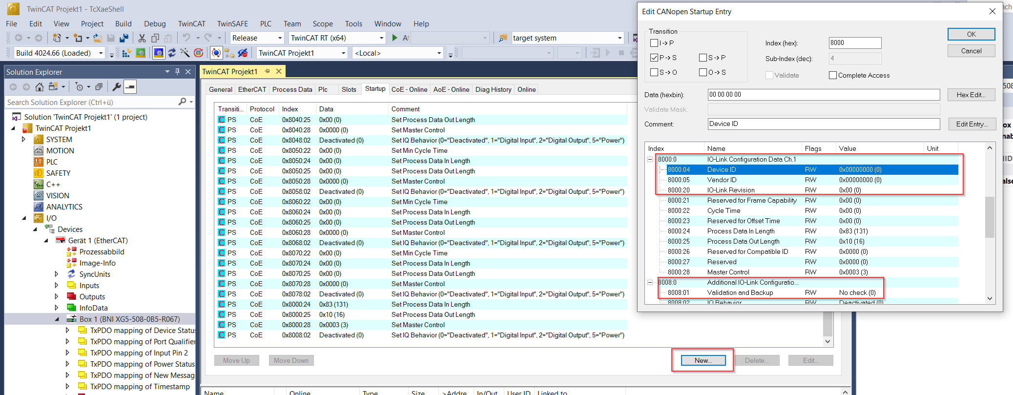
The subindices 0x04 (Device ID), 0x05 (Vendor ID) and 0x20 (IO-Link Revision) from index 0x80n0 (IO-Link Configuration Data Ch. n) need to be added and the subindex 0x01 (Validation and Backup) from index 0x80n8 (Additional IO-Link Configuration Data Ch. n) needs to be added to the list.
Configure the subindex 0x01 (Validation and Backup) from index 0x80n8 (Additional IO-Link Configuration Data Ch. n) with the desired value.
Input the expected Vendor ID, Device ID and IO-Link protocol version.
Validation checks the Vendor ID and Device ID of the connected IO-Link device, as well as its IO-Link protocol version (V1.0 or V1.1). The expected Vendor ID and Device ID must be configured in subindex 0x05 (Vendor ID) and subindex 0x04 (Device ID) of the IO-Link Configuration Data Ch. x object, see IO-Link Configuration Data Ch. x (0x8000 – 0x8FFF).
No check: Validation is deactivated and every device is accepted.
V1.0 Device, no Datastorage: Only devices of IO-Link protocol version V1.0 matching the configured Vendor ID and Device ID are accepted. No data storage, only validation active.
V1.1 Device, no Datastorage: Only devices of IO-Link protocol version V1.1 matching the configured Vendor ID and Device ID are accepted. No data storage, only validation active.
V1.1 Device, Backup + Restore: Only devices of IO-Link protocol version V1.1 matching the configured Vendor ID and Device ID are accepted. The parameter data of the connected device is additionally saved in the network module’s parameter server (remanent memory). As soon as a device requests an upload (upload flag set), or no data is stored yet, the master uploads and backs up the device’s parameter data. If the stored parameter data differs from a newly connected device, the master downloads and restores it to the device.
V1.1 Device, Restore: Only devices of IO-Link protocol version V1.1 matching the configured Vendor ID and Device ID are accepted. The parameter server only downloads and restores previously stored parameter data to the connected device. No upload or backup of new parameter data is performed.
Note
After uploading the parameter data, the Vendor ID and Device ID of the connected IO-Link device remain stored until the data records are deleted.
Validation takes place when the connected IO-Link device is started up. Only an IO-Link device of the same type can be used for data storage.
In order to use a different type of IO-Link device, the content of the parameter server must be deleted. There is no read or write access to the content of the parameter server via EtherCAT.
Note
Upload flag at IO-Link device
The upload flag is required in order to overwrite data already saved in the parameter server with new parameter data of the same IO-Link device.
In order to activate the upload flag of an IO-Link device, the value 0x05 must be
entered in the parameter Index 0x02, Subindex 0.