Object Dictionary
The object directory is largely shared across the EtherCAT variants, with a small set of variant-specific objects.
This section is organized by object groups and marks variant-specific behavior explicitly.
Variant coverage overview
Object |
Index |
BNI XG1-505-0A5-R067 |
BNI XG3-302-0B5-R067 |
BNI XG3-302-1B5-Z067 |
BNI XG3-508-0B5-R067 |
BNI XG5-508-0B5-P067 |
BNI XG5-508-0B5-R067 |
BNI XG5-538-0B5-R067 |
BNI XG5-508-1B5-Z067 |
BNI XG5-538-1B5-Z067 |
|---|---|---|---|---|---|---|---|---|---|---|
0x1000 |
✅ |
✅ |
✅ |
✅ |
✅ |
✅ |
✅ |
✅ |
✅ |
|
0x1001 |
✅ |
✅ |
✅ |
✅ |
✅ |
✅ |
✅ |
✅ |
✅ |
|
0x1008 |
✅ |
✅ |
✅ |
✅ |
✅ |
✅ |
✅ |
✅ |
✅ |
|
0x1009 |
✅ |
✅ |
✅ |
✅ |
✅ |
✅ |
✅ |
✅ |
✅ |
|
0x100A |
✅ |
✅ |
✅ |
✅ |
✅ |
✅ |
✅ |
✅ |
✅ |
|
0x1018 |
✅ |
✅ |
✅ |
✅ |
✅ |
✅ |
✅ |
✅ |
✅ |
|
0x10F1 |
✅ |
✅ |
✅ |
✅ |
✅ |
✅ |
✅ |
✅ |
✅ |
|
0x10F3 |
✅ |
✅ |
✅ |
✅ |
✅ |
✅ |
✅ |
✅ |
✅ |
|
0x10F8 |
✅ |
✅ |
✅ |
✅ |
✅ |
✅ |
✅ |
✅ |
✅ |
|
0x160n[1] |
✅ |
✅ |
✅ |
✅ |
✅ |
✅ |
✅ |
✅ |
✅ |
|
0x1690 |
❌ |
✅ |
✅ |
✅ |
✅ |
✅ |
✅ |
✅ |
✅ |
|
0x1A0n[1] |
✅ |
✅ |
✅ |
✅ |
✅ |
✅ |
✅ |
✅ |
✅ |
|
0x1A80[2] |
✅ |
❌ |
❌ |
✅ |
✅ |
✅ |
✅ |
✅ |
✅ |
|
0x1A90 |
✅ |
✅ |
✅ |
✅ |
✅ |
✅ |
✅ |
✅ |
✅ |
|
0x1A91 |
✅ |
✅ |
✅ |
✅ |
✅ |
✅ |
✅ |
✅ |
✅ |
|
0x1A92 (object 0x10F3:04) |
✅ |
✅ |
✅ |
✅ |
✅ |
✅ |
✅ |
✅ |
✅ |
|
0x1A93 (object 0x10F8:00) |
✅ |
✅ |
✅ |
✅ |
✅ |
✅ |
✅ |
✅ |
✅ |
|
0x1C00 |
✅ |
✅ |
✅ |
✅ |
✅ |
✅ |
✅ |
✅ |
✅ |
|
0x1C12 |
✅ |
✅ |
✅ |
✅ |
✅ |
✅ |
✅ |
✅ |
✅ |
|
0x1C13 |
✅ |
✅ |
✅ |
✅ |
✅ |
✅ |
✅ |
✅ |
✅ |
|
0x1C32 |
✅ |
✅ |
✅ |
✅ |
✅ |
✅ |
✅ |
✅ |
✅ |
|
0x1C33 |
✅ |
✅ |
✅ |
✅ |
✅ |
✅ |
✅ |
✅ |
✅ |
|
0x40n0[3] |
✅ |
❌ |
❌ |
✅ |
✅ |
✅ |
✅ |
✅ |
✅ |
|
0x60n0[3] |
✅ |
✅ |
✅ |
✅ |
✅ |
✅ |
✅ |
✅ |
✅ |
|
0x70n0[3] |
✅ |
✅ |
✅ |
✅ |
✅ |
✅ |
✅ |
✅ |
✅ |
|
0x80n0[3] |
✅ |
❌ |
❌ |
✅ |
✅ |
✅ |
✅ |
✅ |
✅ |
|
0x80n0[3] |
❌ |
✅ |
✅ |
❌ |
❌ |
❌ |
❌ |
❌ |
❌ |
|
0x80n8[3] |
✅ |
❌ |
❌ |
✅ |
✅ |
✅ |
✅ |
✅ |
✅ |
|
0x80n8[3] |
❌ |
✅ |
✅ |
❌ |
❌ |
❌ |
❌ |
❌ |
❌ |
|
0x90n0[3] |
✅ |
❌ |
❌ |
✅ |
✅ |
✅ |
✅ |
✅ |
✅ |
|
0xA0n0[3] |
✅ |
❌ |
❌ |
✅ |
✅ |
✅ |
✅ |
✅ |
✅ |
|
0xF000 |
✅ |
✅ |
✅ |
✅ |
✅ |
✅ |
✅ |
✅ |
✅ |
|
0xF030 |
✅ |
✅ |
✅ |
✅ |
✅ |
✅ |
✅ |
✅ |
✅ |
|
0xF050 |
✅ |
✅ |
✅ |
✅ |
✅ |
✅ |
✅ |
✅ |
✅ |
|
0xF100 (TxPDO 0x1A80[2]) |
✅ |
❌ |
❌ |
✅ |
✅ |
✅ |
✅ |
✅ |
✅ |
|
0xF101 (TxPDO 0x1A81[2]) |
✅ |
❌ |
❌ |
✅ |
✅ |
✅ |
✅ |
✅ |
✅ |
|
0xF500 |
✅ |
✅ |
✅ |
✅ |
✅ |
✅ |
✅ |
✅ |
✅ |
|
0xF501 |
✅ |
✅ |
✅ |
✅ |
✅ |
✅ |
✅ |
✅ |
✅ |
|
0xF502 |
✅ |
✅ |
✅ |
✅ |
✅ |
✅ |
✅ |
✅ |
✅ |
|
0xF503 |
✅ |
✅ |
✅ |
✅ |
✅ |
✅ |
✅ |
✅ |
✅ |
|
0xF510 |
❌ |
❌ |
❌ |
❌ |
❌ |
❌ |
✅ |
❌ |
✅ |
|
0xF511 |
✅ |
✅ |
✅ |
✅ |
✅ |
✅ |
✅ |
✅ |
✅ |
|
0xF600 |
✅ |
✅ |
✅ |
✅ |
✅ |
✅ |
✅ |
✅ |
✅ |
|
0xF601 |
✅ |
✅ |
✅ |
✅ |
✅ |
✅ |
✅ |
✅ |
✅ |
|
0xF700 |
❌ |
✅ |
✅ |
✅ |
✅ |
✅ |
✅ |
✅ |
✅ |
Note
Object naming is identical across variants wherever possible. Index and subindex definitions for a concrete product code always follow the corresponding ESI.
Detailed Objects Description
The following section will describe all the Objects mentioned in Variant coverage overview in detail.
Device type (0x1000)
Subindex |
Name |
DataType |
Access |
|---|---|---|---|
0x00 |
Device type |
UDINT |
RO |
Error register (0x1001)
Subindex |
Name |
DataType |
Access |
|---|---|---|---|
0x00 |
Error register |
USINT |
RO |
Device Name (0x1008)
Subindex |
Name |
DataType |
Access |
|---|---|---|---|
0x00 |
Device Name |
STRING(20) |
RO |
Hardware Version (0x1009)
Subindex |
Name |
DataType |
Access |
|---|---|---|---|
0x00 |
Hardware Version |
STRING(5) |
RO |
Software Version (0x100A)
Subindex |
Name |
DataType |
Access |
|---|---|---|---|
0x00 |
Software Version |
STRING(5) |
RO |
Identity Object (0x1018)
Subindex |
Name |
DataType |
|---|---|---|
0x00 |
Number of entries |
USINT |
0x01 |
Vendor ID |
UDINT |
0x02 |
Product Code |
UDINT |
0x03 |
Revision Number |
UDINT |
0x04 |
Serial number |
UDINT |
Error Settings (0x10F1)
Subindex |
Name |
DataType |
|---|---|---|
0x00 |
Number of entries |
USINT |
0x01 |
Local Error Reaction |
UDINT |
0x02 |
Sync Error Counter Limit |
UINT |
Diagnosis History (0x10F3)
Subindex |
Name |
DataType |
|---|---|---|
0x00 |
Number of entries |
USINT |
0x01 |
Maximum Messages |
USINT |
0x02 |
Newest Message |
USINT |
0x03 |
Newest Acknowledged Message |
USINT |
0x04 |
New Messages Available |
BOOL |
0x05 |
Flags |
UINT |
Subindex 0x04 (New Messages Available) is also mapped to the process data via Map TxPDO New Messages Available (0x1A92).
Timestamp Object (0x10F8)
Index |
Subindex |
Name |
DataType |
Access |
|---|---|---|---|---|
0x10F8 |
0x00 |
Timestamp Object |
ULINT |
RO |
This object is mapped to TxPDO via Map TxPDO Timestamp (0x1A93).
RxPDO mapping Ch. x (0x160n)
This generic mapping object links the channel-specific slot module to the raw process data object Output Data Ch. x and applies to all variants.
Index |
Name |
Access |
|---|---|---|
0x160n[1] |
RxPDO mapping of Ch. x |
RO |
RxPDO mapping of Output Pin 2 (0x1690)
This mapping object applies to variants with output pin 2 (all listed variants except BNI XG1-505-0A5-R067).
Index |
Name |
Access |
|---|---|---|
0x1690 |
RxPDO mapping of Output Pin 2 |
RO |
TxPDO mapping Ch. x (0x1A0n)
This generic mapping object links the channel-specific slot module to the raw process data object Input Data Ch. x and applies to all variants.
Index |
Name |
Access |
|---|---|---|
0x1A0n[1] |
TxPDO mapping of Ch. x |
RO |
TxPDO mapping of Device Status (0x1A80)
Note
Please check whether IO-Link is supported by your module before using this function. For more information on product variants that support IO-Link, see Supported product variants
Index |
Subindex |
Name |
DataType |
Access |
|---|---|---|---|---|
0x1A80 |
0x00 |
Number of mapped entries |
USINT |
RO |
0x01 |
Mapped object 1 |
UDINT |
RO |
|
0x02 |
Mapped object 2 |
UDINT |
RO |
|
0x03 |
Mapped object 3 |
UDINT |
RO |
|
0x04 |
Mapped object 4 |
UDINT |
RO |
|
0x05 |
Mapped object 5 |
UDINT |
RO |
|
0x06 |
Mapped object 6 |
UDINT |
RO |
|
0x07 |
Mapped object 7 |
UDINT |
RO |
|
0x08 |
Mapped object 8 |
UDINT |
RO |
Subindices 0x01 to 0x08 map Device Status
subindices 0x01 to 0x08 (one status byte per port) into the TxPDO.
For the status byte value coding, see Device Status (0xF100).
Map TxPDO input pin 2 (0x1A90)
This TxPDO mapping object applies to all listed variants.
Index |
Subindex |
Name |
DataType |
Access |
|---|---|---|---|---|
0xF600 |
0x00 |
Input Pin 2 |
BITARR8 |
RO |
This object maps Input Pin 2 (0xF600) to TxPDO.
Map TxPDO pin 4 (0x1A0n)
Index range |
Subindex |
Name |
DataType |
Access |
|---|---|---|---|---|
0x6xxx |
module-specific |
Module-specific TxPDO input data (pin 4 mapping) |
Variable, see ESI module |
RO |
0x7xxx |
module-specific |
Module-specific RxPDO output data (pin 4 mapping) |
Variable, see ESI module |
RW |
The following index range applies in a modular EtherCAT device:
0x6xxx is a module-specific input range for TxPDO data.
0x7xxx is a module-specific output range for RxPDO data.
IO-Link data is up to 32 bytes for input and output.
If a connection is configured as a digital input or digital output, the value of pin 4 is mapped to data byte 0, bit 0.
Map TxPDO PowerStatus (0x1A91)
This TxPDO mapping object applies to all listed variants.
Index |
Subindex |
Name |
DataType |
Access |
|---|---|---|---|---|
0xF601 |
0x01 |
Global status, see Global status values (Subindex 0x01) |
UINT8 |
RO |
0x02 |
Short circuit in the sensor supply; one bit for each port |
UINT8 |
RO |
|
0x03 |
Short circuit at pin 4 of the actuator supply, one bit for each port |
UINT8 |
RO |
|
0x04 |
Short circuit at pin 2 of the actuator supply, one bit for each port |
UINT8 |
RO |
This object maps Power Status (0xF601) to TxPDO.
Global status values (Subindex 0x01)
Bit |
Description |
|---|---|
0 |
Sensor supply low (1 = low, 0 = OK) |
1 |
Actuator supply low (1 = low, 0 = OK) |
Map TxPDO New Messages Available (0x1A92)
Index |
Subindex |
Name |
DataType |
Access |
|---|---|---|---|---|
0x10F3 |
0x04 |
New Messages Available |
BOOL |
RO |
Map TxPDO Timestamp (0x1A93)
Index |
Subindex |
Name |
DataType |
Access |
|---|---|---|---|---|
0x10F8 |
0x00 |
Timestamp Object |
ULINT |
RO |
This object maps Timestamp Object (0x10F8) to TxPDO.
Sync manager type (0x1C00)
Sync manager objects are configured automatically by the EtherCAT master during PDO assignment and normally do not need to be accessed directly.
Index |
Name |
|---|---|
0x1C00 |
Sync manager type |
SyncManager 2 Assign / RxPDO (0x1C12)
Sync manager objects are configured automatically by the EtherCAT master during PDO assignment and normally do not need to be accessed directly.
Index |
Name |
|---|---|
0x1C12 |
SyncManager 2 Assign (RxPDO) |
SyncManager 3 Assign / TxPDO (0x1C13)
Sync manager objects are configured automatically by the EtherCAT master during PDO assignment and normally do not need to be accessed directly.
Index |
Name |
|---|---|
0x1C13 |
SyncManager 3 Assign (TxPDO) |
SM output parameter (0x1C32)
Sync manager objects are configured automatically by the EtherCAT master during PDO assignment and normally do not need to be accessed directly.
Index |
Name |
|---|---|
0x1C32 |
SM output parameter |
SM input parameter (0x1C33)
Sync manager objects are configured automatically by the EtherCAT master during PDO assignment and normally do not need to be accessed directly.
Index |
Name |
|---|---|
0x1C33 |
SM input parameter |
ISDU read/write Ch. x (0x4000 – 0x4FFF)
Note
Please check whether IO-Link is supported by your module before using this function. For more information on product variants that support IO-Link, see Supported product variants
Index |
Sub-index |
Name |
DataType |
Access |
|---|---|---|---|---|
0x40n0 |
0x00 |
Number of entries |
UINT8 |
RO |
0x01 |
Control |
UINT8 |
RW |
|
0x02 |
Status |
UINT8 |
RO |
|
0x03 |
Index |
UINT16 |
RW |
|
0x04 |
Subindex |
UINT8 |
RW |
|
0x05 |
Length |
UINT8 |
RW |
|
0x06 |
Data |
ARRAY [0…231] OF BYTE |
RW |
|
n = 0…7 |
0x07 |
Error Code |
UINT16 |
RW |
Control values (Subindex 0x01)
Value (UINT8) |
Function |
|---|---|
0 |
no control action |
2 |
write |
3 |
read |
Status values (Subindex 0x02)
Value (UINT8) |
Status |
|---|---|
0 |
no activity |
1 |
busy |
2 |
success |
4 |
error |
0xFF |
failure |
Input Data Ch. x (0x60n0)
This object holds the raw input process data for each channel, referenced by TxPDO mapping Ch. x (0x1A0n).
Index |
Name |
DataType |
Access |
|---|---|---|---|
0x60n0[3] |
Input Data Ch. x |
See ESI |
RO |
Output Data Ch. x (0x70n0)
This object holds the raw output process data for each channel, referenced by RxPDO mapping Ch. x (0x160n).
Index |
Name |
DataType |
Access |
|---|---|---|---|
0x70n0[3] |
Output Data Ch. x |
See ESI |
RW |
IO-Link Configuration Data Ch. x (0x8000 – 0x8FFF)
Note
Please check whether IO-Link is supported by your module before using this function. For more information on product variants that support IO-Link, see Supported product variants
Index |
Sub-index |
Name |
DataType |
Access |
Value/Description |
|---|---|---|---|---|---|
0x80n0, n = 0…7 |
0x00 |
Number of entries |
USINT |
RO |
|
0x04 |
Device ID |
UDINT |
RW |
||
0x05 |
Vendor ID |
UDINT |
RW |
||
0x20 |
IO-Link Revision |
USINT |
RW |
0x10 or 0x11 |
|
0x21 |
Reserved for Frame Capability |
USINT |
RW |
Not in use |
|
0x22 |
Cycle Time |
USINT |
RW |
Cycle time |
|
0x23 |
Reserved for Offset Time |
USINT |
RW |
Not in use |
|
0x24 |
Process Data In Length |
USINT |
RW |
Maximum length |
|
0x25 |
Process Data Out Length |
USINT |
RW |
Maximum length |
|
0x26 |
Reserved for Compatible ID |
UINT |
RW |
Not in use |
|
0x27 |
Reserved |
UINT |
RW |
Not in use |
|
0x28 |
Master Control |
UINT |
RW |
See ethercat/configuration-without-esi |
Additional IO-Link Configuration Data Ch. x (IO-Link variants)
Note
Please check whether IO-Link is supported by your module before using this function. For more information on product variants that support IO-Link, see Supported product variants
Index |
Sub-index |
Name |
DataType |
Access |
Value/Description |
|---|---|---|---|---|---|
0x80n8, n = 0…7 |
0x00 |
Number of entries |
USINT |
RO |
|
0x01 |
Validation and Backup |
USINT |
RW |
See values below |
|
0x02 |
IQ Behavior |
USINT |
RW |
See values below |
Values for Validation and Backup (Subindex 0x01)
Value |
Function |
|---|---|
0 |
No check |
1 |
V1.0 Device, no Datastorage |
2 |
V1.1 Device, no Datastorage |
3 |
V1.1 Device, Backup + Restore |
4 |
V1.1 Device, Restore |
Values for IQ Behavior (Subindex 0x02)
Value |
Function |
|---|---|
0 |
Deactivated |
1 |
Digital Input |
2 |
Digital Output |
5 |
Power |
Available values depend on the port hardware.
Configuration Data Ch. x (XG3-302)
Index |
Sub-index |
Name |
DataType |
Access |
Value/Description |
|---|---|---|---|---|---|
0x8000, 0x8010, …, 0x8070 |
0x01 |
Pin 4 Behavior |
UINT8 |
RW |
One object per channel (Ch.1 … Ch.8) |
Additional Configuration Data Ch. x (XG3-302)
This object group contains additional channel-specific configuration.
Index |
Sub-index |
Name |
DataType |
Access |
Value/Description |
|---|---|---|---|---|---|
0x8008, 0x8018, …, 0x8078 |
0x01 |
Pin 2 Behavior |
UINT8 |
RW |
One object per channel (Ch.1 … Ch.8) |
IO-Link Information Data Ch. x (0x9000 – 0x9FFF)
Note
Please check whether IO-Link is supported by your module before using this function. For more information on product variants that support IO-Link, see Supported product variants
Index |
Subindex |
Name |
DataType |
Access |
|---|---|---|---|---|
0x90n0, n = 0…7 |
0x04 |
Device ID |
UINT32 |
RO |
0x05 |
Vendor ID |
UINT32 |
RO |
|
0x20 |
IO-Link revision |
UINT8 |
RO |
|
0x22 |
Min Cycle Time |
UINT8 |
RO |
|
0x24 |
Process Data In Length |
UINT8 |
RO |
|
0x25 |
Process Data Out Length |
UINT8 |
RO |
IO-Link Diagnosis Data Ch. x (0xA000 – 0xAFFF)
Note
Please check whether IO-Link is supported by your module before using this function. For more information on product variants that support IO-Link, see Supported product variants
Index |
Subindex |
Name |
DataType |
Access |
|---|---|---|---|---|
0xA0n0, n = 0…7 |
0x01 |
IO-Link state |
UINT8 |
RO |
0x02 |
Lost Frames |
UINT8 |
RO |
Values for IO-Link state (Subindex 0x01)
Value |
Status of IO-Link Port |
|---|---|
0 |
Deactivated |
1 |
Digital Input |
2 |
Digital Output |
3 – 7 |
Reserved |
8 |
IO-Link Operate |
9 |
IO-Link Stop |
Values for Lost Frames (Subindex 0x02)
This parameter counts lost IO-Link Frames (M sequence repeats).
Two repeat attempts are generally added when changing the device. This value is only reset to zero during the start. The value is updated regularly, for example once a second.
Modular Device Profile (0xF000)
Index |
Name |
Access |
|---|---|---|
0xF000 |
Modular Device Profile |
RO |
Configured Module Ident List (0xF030)
Index |
Name |
Access |
|---|---|---|
0xF030 |
Configured Module Ident List |
RW |
Detected Module Ident List (0xF050)
Index |
Name |
Access |
|---|---|---|
0xF050 |
Detected Module Ident List |
RO |
Device Status (0xF100)
Note
Please check whether IO-Link is supported by your module before using this function. For more information on product variants that support IO-Link, see Supported product variants
Index |
Subindex |
Name |
DataType |
Access |
|---|---|---|---|---|
0xF100 |
0x01 |
Status of IO-Link Port 1 |
UINT8 |
RO |
0x02 |
Status of IO-Link Port 2 |
UINT8 |
RO |
|
0x03 |
Status of IO-Link Port 3 |
UINT8 |
RO |
|
0x04 |
Status of IO-Link Port 4 |
UINT8 |
RO |
|
0x05 |
Status of IO-Link Port 5 |
UINT8 |
RO |
|
0x06 |
Status of IO-Link Port 6 |
UINT8 |
RO |
|
0x07 |
Status of IO-Link Port 7 |
UINT8 |
RO |
|
0x08 |
Status of IO-Link Port 8 |
UINT8 |
RO |
The CoE object Device Status (0xF100) is mapped as TxPDO mapping of status data (TxPDO 0x1A80) to the process data.
Device status coding
The lower nibble (0x_?) encodes the port mode/state.
Value |
Meaning |
|---|---|
0x_0 |
Port disabled |
0x_1 |
Port in standard digital input |
0x_2 |
Port in standard digital output |
0x_3 |
Port in communication OP |
0x_4 |
Port in communication COMSTOP |
The upper nibble (0x?_) encodes diagnostic/error information.
Value |
Meaning |
|---|---|
0x0_ |
No error |
0x3_ |
Invalid device ID |
0x4_ |
Invalid vendor ID |
0x5_ |
Invalid IO-Link version |
0x7_ |
Invalid cycle time |
0x8_ |
Invalid process data input length |
0x9_ |
Invalid process data output length |
0xA_ |
No device detected |
Port Qualifier (0xF101)
Note
Please check whether IO-Link is supported by your module before using this function. For more information on product variants that support IO-Link, see Supported product variants
Index |
Subindex |
Name |
DataType |
Access |
|---|---|---|---|---|
0xF101 |
0x01 |
Port Qualifier Port 1 |
UINT8 |
RO |
0x02 |
Port Qualifier Port 2 |
UINT8 |
RO |
|
0x03 |
Port Qualifier Port 3 |
UINT8 |
RO |
|
0x04 |
Port Qualifier Port 4 |
UINT8 |
RO |
|
0x05 |
Port Qualifier Port 5 |
UINT8 |
RO |
|
0x06 |
Port Qualifier Port 6 |
UINT8 |
RO |
|
0x07 |
Port Qualifier Port 7 |
UINT8 |
RO |
|
0x08 |
Port Qualifier Port 8 |
UINT8 |
RO |
The CoE object Port Qualifier (0xF101) is mapped as TxPDO mapping of port qualifier (TxPDO 0x1A81) to the process data.
Port qualifier bits
Bit |
Description |
4 |
PortActive / Port activated 1 = Port can be used. 0 = Port deactivated. |
5 |
DevCom / device is ready for operation 1 = Device detected and in status Operate. 0 = Everything else. |
6 |
DevErr / device error 1 = Error occurred (validation error, short circuit, etc.). 0 = OK. |
7 |
PQ / validity of input data of IO-Link device 1 = Valid. 0 = Invalid. |
Firmware Build Information (0xF500)
Index |
Subindex |
Name |
DataType |
Access |
|---|---|---|---|---|
0xF500 |
0x00 |
Number of entries |
USINT |
RO |
0x01 |
Build Number |
UDINT |
RO |
|
0x02 |
Build Hash Id |
STRING(8) |
RO |
|
0x03 |
Firmware Version |
STRING(12) |
RO |
Product Identification (0xF501)
Index |
Subindex |
Name |
DataType |
Access |
|---|---|---|---|---|
0xF501 |
0x00 |
Number of entries |
USINT |
RO |
0x01 |
Product Name |
STRING(24) |
RO |
|
0x02 |
Serial Number |
STRING(16) |
RO |
|
0x03 |
Order Code |
STRING(8) |
RO |
Fieldbus Information (0xF502)
Index |
Subindex |
Name |
DataType |
Access |
|---|---|---|---|---|
0xF502 |
0x00 |
Number of entries |
USINT |
RO |
0x01 |
Current Protocol |
DT0803EN08 |
RO |
|
0x02 |
Protocol After Reboot |
DT0803EN08 |
RW |
Subindex 0x01 reports the currently active fieldbus protocol.
Subindex 0x02 selects the fieldbus protocol that the device will use after a
restart.
Protocol values
Value |
Meaning |
|---|---|
0 |
AUTODETECT |
1 |
ETHERCAT |
2 |
ETHERNET_IP |
3 |
PROFINET |
4 |
MODBUS_TCP |
6 |
IOT |
7 |
ETHERCAT_FHC |
Module Reboot (0xF503)
The requested action is written to subindex 0x01 and executed through the trigger
bit at subindex 0x02.
Index |
Subindex |
Name |
DataType |
Access |
|---|---|---|---|---|
0xF503 |
0x00 |
Number of entries |
USINT |
RO |
0x01 |
Action |
DT0804EN08 |
RW |
|
0x02 |
Trigger |
BOOL |
RW |
Subindex 0x01 selects the reboot action.
Subindex 0x02 triggers execution of the selected action.
Action values
Value |
Meaning |
|---|---|
0 |
NO ACTION |
1 |
REBOOT |
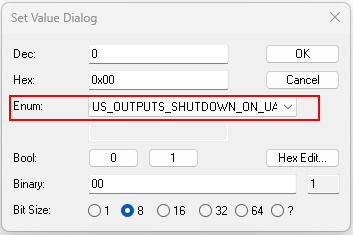
Module Settings (0xF510)
Using CoE object 0xF510 (Module Settings), it is possible to modify the output power loss behavior.
Note
Only available for the XG5-538-… variants.
Index |
Subindex |
Name |
DataType |
Access |
Value/Description |
|---|---|---|---|---|---|
0xF510 |
0x00 |
Number of entries |
USINT |
RO |
|
0x01 |
Output Powerloss Behavior |
USINT |
RW |
See values below |
The parameter defines what happens to active outputs on Pin 2 and Pin 4 when UA voltage is lost.
Value 0 – US Outputs shutdown on UA powerloss
All active outputs on Pin 2 and Pin 4 are automatically switched off in the event of a UA voltage drop. This matches the behavior of a XG5-508-… master, even though Pin 2 and Pin 4 of Class A output ports are supplied by US, and Pin 4 of Class B ports are supplied by UA.
Value 1 – Hardware Defined
US powered outputs will not be switched off in the event of a UA voltage drop. All outputs remain in their current state. Only Class B Pin 2 outputs are physically supplied by UA and will therefore be shut down.
First step

Second step
IOT Settings (0xF511)
Index |
Name |
Access |
|---|---|---|
0xF511 |
IOT Settings |
RW |
Input Pin 2 (0xF600)
Index |
Name |
DataType |
Access |
|---|---|---|---|
0xF600 |
Input Pin 2 |
BITARR8 |
RO |
Power Status (0xF601)
Index |
Subindex |
Name |
DataType |
Access |
|---|---|---|---|---|
0xF601 |
0x01 |
Global status, see Global status values (Subindex 0x01) |
UINT8 |
RO |
0x02 |
Short circuit in the sensor supply; one bit for each port |
UINT8 |
RO |
|
0x03 |
Short circuit at pin 4 of the actuator supply, one bit for each port |
UINT8 |
RO |
|
0x04 |
Short circuit at pin 2 of the actuator supply, one bit for each port |
UINT8 |
RO |
Output Pin 2 (0xF700)
This CoE object applies to variants with output pin 2 (all listed variants except BNI XG1-505-0A5-R067).
Index |
Name |
DataType |
Access |
|---|---|---|---|
0xF700 |
Output Pin 2 |
BITARR8 |
RO |