IO-Link basics
General
IO-Link integrates conventional and intelligent sensors and actuators in automation systems and is intended as a communication standard below classic field buses. Fieldbus-independent transfer uses communication systems that are already available (field buses or Ethernet-based systems).
IO-Link devices, such as sensors and actuators, are connected to the controlling system using a point-to-point connection via a gateway, the IO-Link master. The IO-Link devices are connected using commercially available unshielded standard sensor cables.
Communication is based on a standard UART protocol with a 24-V pulse modulation in half-duplex operation. This allows classic three-conductor physics.
Protocol
With IO-Link communication, permanently defined frames are cyclically exchanged between the IO-Link master and the IO-Link device. In this protocol, both process and required data, such as parameters or on demand data, is transferred. The size and the type of the frame and the cycle time used result from the combination of master and device features. (see communication properties in section Communication parameters).
Cycle Time
The cycle time used (master cycle time) results from the minimum possible cycle time of the IO-Link device (min cycle time, see chapter Communication parameters) and the minimum possible cycle time of the IO-Link master. When selecting the IO-Link master, please note that the larger value determines the cycle time used.
Communication parameters
In order to be able to establish a stable communication connection between master and device, the master requests some important communication parameters from the device at the start of communication. Settings for communication in Preoperate and Operate modes are influenced by the parameters and the device is clearly identified.
Communication parameters are described in the chapter Communication parameters.
Process Data Flow
The data transfer is based on the general profile specification (IO-Link Common Profile 1.0, see Fig. Example of a PDinput data flow for example).
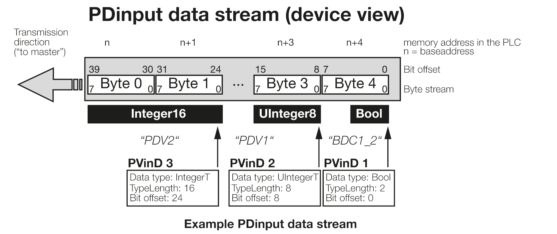
The highest value byte (MSB, designated as Byte 0 ) is transferred first and can be found in the PLC under the lowest storage address. The lowest value byte (LSB) is transferred last and has the highest byte number (designated in Fig. Example of a PDinput data flow as Byte 4).
For word-based data types (> 8 bit) this means that the byte at the lowest address is the highest value byte, while the highest address contains the lowest value byte.
The description of the data flow structure in IODD uses bit offsets. Offset 0 means the least significant bit of the last byte.
Process data variables (in Fig. Example of a PDinput data flow PDV1, PDV2) are aligned to the byte limits in most cases.
Binary information (BDC) is transferred in the lowest value byte in most cases.
Process data objects
The process data flow is made up of various process data objects, which are not only shown in the process data flow, but are also used for the internal exchange of information between functions.
For example, PdObjects can be used to monitor threshold values in the device and trigger a warning if a limit is exceeded, or to provide status information such as the switching state directly in the process data.
Therefore, a unique object ID is assigned to this individual information, which can be used at different places.
Process data objects are described in the function chapters under Process Data.
Device Status
The Device Status indicates the current status of the device or of the directly connected peripherals. This functionality is part of the IO-Link specification.
The following states are output by the device:
Device is operating properly (device is functioning error-free)
This status indicates that no serious error has occurred in the device and the device can be operated without restrictions.Maintenance-Required
Although the process data is valid, internal diagnosis functions show that the device or the operational environment of the device should be serviced.Out-of-Specification
Although the process data is valid, internal diagnosis functions show that the device is operating outside of its specification. This can affect both the measurement application itself as well as the environmental conditions.Functional Check
Process data is temporarily invalid while a deliberate intervention is performed on the device. For example, parameterization processes or teach-in.Failure
The device or the connected peripherals have a severe error. The device cannot perform its intended function!
For further information, see section Device status and detailed device status.
The creation of the Device Status is always based on the output of diagnosis messages. A Device Status is output for every diagnosis message (event). Each of these can be found in the event overview list (see section Events or in the description of the functions).
Block Parameterization
Block parameterization refers to a special process in which multiple parameters are parameterized in one process. It is started with a start command and concluded with an end command.
Because the check of the data is not performed until the parameterization is concluded, pieces of data that are dependent on one another can also be set without problem.
The System Commands 0x01…0x06 are also part of the Parameter Manager (see System commands).
The functionality and processes are described in the IO-Link specification.
Data Storage
Data Storage refers to a special process for being able to store the parameterization data of a device on the master. The master controls the process between uploads (if data is intentionally changed) or downloads (if, e.g., an incorrectly parameterized device is connected). The system comprising master and device thereby ensures that a device can be exchanged without the need for an active re-parameterization.
Operation is dependent on the used IO-Link master and is explained in the corresponding description.
Variant Handling
A device can contain several different IO-Link devices. These device variants differ in the basic functionality, the IO-Link communication settings (length of the process data, communication speed) or in the IO-Link communication model or data model (e.g., support of other ISDU parameters or IO-Link profiles).
A variant can be selected via an ISDU access (see function Variant Configuration). Note here, that changes do not take effect until after a communication restart (e.g., through Device Reset (see Reset Commands)).
All device variants can also be selected via the so-called Compatibility Mode. In this case, the port configuration on the master is used to switch the device to the target variant, which is then used permanently by the device.
Reset Commands
The device offers various reset functions. A corresponding command is executed via a system command.
The behavior and the values that are reset in a given case can be found in the ISDU overview (see section ISDU and in the individual function descriptions).
The Reset Commands are described in the corresponding chapter.
Device Functions and Master Gateway
The functions of the device are described in detail in the subsequent sections. Refer to the guide of the IO-Link master for information on the implementation of the process, parameter and diagnostic data via the master gateway.