Radar frontend
Description
This device utilizes a Frequency Modulated Continuous Wave (FMCW) radar. An FMCW radar operates by emitting a continuous radio frequency signal whose frequency increases or decreases linearly over a set period, forming what is known as a “chirp.” When this signal encounters an object, part of it is reflected back to the radar sensor. Because the reflected signal travels a longer path, it arrives with a time delay compared to the transmitted signal, resulting in a frequency difference known as the beat frequency.
The radar frontend captures both the transmitted and received signals and mixes them to generate the beat frequency signal. This signal contains information about the distance to the reflecting object. The device samples the beat frequency signal and processes it using a Fast Fourier Transform (FFT), which converts the signal from the time domain to the frequency domain. In the resulting FFT spectrum, each peak represents a potential target at a specific range.
Depending on the configuration, the processing algorithm searches for the strongest peak or the closest peak in the FFT magnitude spectrum. The position of the peak in the frequency spectrum is used to calculate the range to the target, based on the known properties of the chirp signal and the radar’s configuration. The amplitude of the peak provides a measure of the signal strength, which can be interpreted as the reflectivity or size of the target.
The Radar Frontend outputs two main values: the calculated range of the target and the corresponding signal strength.
Mathematics/Algorithm
The processing of the output of the Radar Frontend HW involves the following steps:
Distance/Object detection variant
Signal processing: The radar frontend samples the analog signals using an ADC. After derivation and windowing the sampled data, an FFT is performed to convert the signals to the frequency domain. The magnitude spectrum is then calculated from the FFT output for further analysis.
Peak Search: The algorithm searches within Minimum distance for target search and Maximum distance for target search for the most significant peak or the first peak in the magnitude spectrum, which is bigger than the Minimum target strength.
Distance Calculation: The frequency position of the detected peak is used to calculate the distance to the target, based on the radar’s chirp parameters.
Moving Window Averaging: The calculated distance values may be averaged over a moving window to smooth out measurement noise and improve stability. (see Number of averaging)
Output of Measurement Value: The final, processed measurement value (distance and signal strength) output is provided.
Radar reflex gate variant
Signal processing: The radar frontend samples the analog signals using an ADC. After derivation a DFT is calculated for one specified frequency which corresponds to the Reflector distance. The result of the calculation is the signal strength at this distance.
Output of Measurement Value: The signal strength is converted to dB and provided to the output.
Process Data
The process data items listed in here are used only internally to provide data to the measurement frontend.
| Object ID | Name | Description |
|---|---|---|
| 0x0025 (37) | Transducer Value High Resolution | Distance output |
| 0x0175 (373) | Transducer Value High Resolution 2 | Target Strength output |
ISDU
| Name | Index | Subindex | Access | Length | Data Type | Data Storage | Default |
|---|---|---|---|---|---|---|---|
| Radar Sensor Configuration | 0x010F (271) | 0 | R/W | 9 bytes | n/a | 0x00 | |
| Number of averaging | 1 | R/W | 2 bytes | UINT16 | Yes | 10 | |
| Target search mode | 2 | R/W | 1 byte | UINT8(ENUM) | Yes | 0 | |
| Minimum distance for target search | 3 | R/W | 2 bytes | UINT16 | Yes | 150 | |
| Maximum distance for target search | 4 | R/W | 2 bytes | UINT16 | Yes | 15000 | |
| Minimum target strength | 5 | R/W | 2 bytes | UINT16 | Yes | 300 | |
| Radar Reflex Gate variant only | |||||||
| Set reflector distance | 0x140 (320) | 0 | W | 2 bytes | UINT16 | Yes | |
| Get reflector distance | 0x141 (321) | 0 | R | 2 bytes | UINT16 | 500 | |
Number of averaging
The distance output is calculated by averaging the last N measurements.
Target search mode
| Value | Description |
|---|---|
| 0x00 | Strongest Target |
| 0x01 | Closest Target |
Minimum distance for target search
The distance (in mm) at which the search for a peak starts.
Maximum distance for target search
The distance (in mm) at which the search for a peak stops.
Minimum target strength
The strength (in dB) that a peak must have to be considered a peak.
Set reflector distance
Only used in Radar Reflex Gate variant. Sets the Distance to the Radar Reflector. Automatically adjusts the distance to a close peak if present.
Read reflector distance
Only used in Radar Reflex Gate variant. Reads back the set (and adjusted) Distance to the Radar Reflector
Variant Dependence
Object Detection and Distance Measurement variant
In Object detection and Distance Measurement variant the sensor can detect one object and provides the Distance and Target Strength of the object in every 1 ms.
The detection depends on the Radar Sensor Configuration parameters Minimum distance, Maximum distance, Minimum target strength and Target search mode as well as on the Measurement Configuration Measurement range. The following figure summarizes these configuration options.
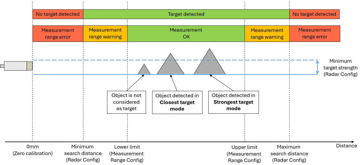 { width=”500” }
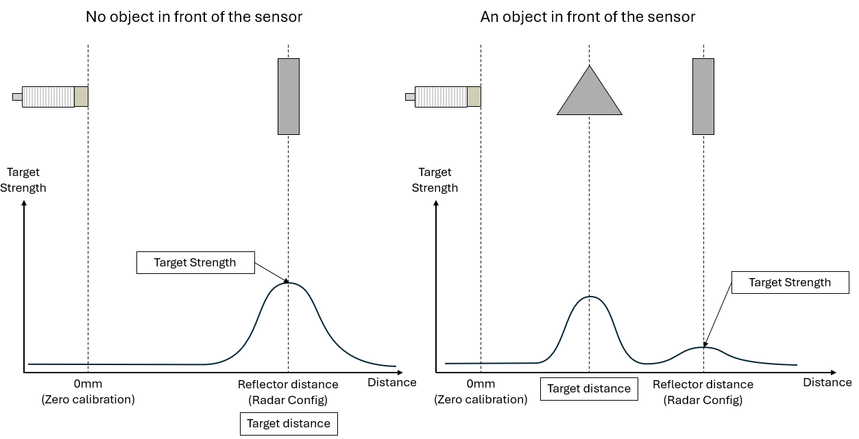
Radar Reflex Gate variant
In Radar Reflex Gate variant the sensor is placed in front of a fixed reflector or background plate and the objects are appearing between the sensor and the reflector. The objects can block or reduce reflected signal from the reflector, thus the Target Strength of the reflector correlates if an object is present or not.
The distance of the reflector is configured by Set reflector distance so the Target Strength output corresponds to the magnitude of the signal at this distance. The Target Strength output is updated every 1ms.
Similarly to in Object detection and Distance measurement variant, the Distance output is provided but the update rate is 10ms. The Distance output calculation uses the same configuration parameters as in the other variant. The Distance output will show the distance of the object, or the reflector.
 { width=”500” }
The ISDUs Set reflector distance and Read reflector distance are only available in Radar Reflex Gate variant.