Switching Profiles
The sensor implements SSP 4.2.2 profile according to the IO-Link specification ‘IO-Link Profile Smart Sensors 2nd Ed’ Version 1.2 from January 2024. In this profile there are two switching channels (SSCx.1 and SSCx.2) per measurement channel.
Description
Sensor Principle / Evaluation Logic
The sensor performs measurement value acquisition as a continuous signal that is evaluated for switching signal generation. The measurement value is only evaluated if it is within this valid measurement range. If the measurement value is outside of this range, the switching channel output switches to low.
Switching points are defined by means of setpoints that can be determined using various teach processes. Alternatively, the setpoints can also be set directly via ISDUs, but under observation of the same requirements and rules as define for the teach processes.
The setpoint setting can also be used to deactivate the switching point evaluation. This is performed with the Setpoint not teached setting:
| Status | Value |
|---|---|
| Setpoint not teached (32 bit) | 2,147,483,644 (0x7FFFFFFC) |
Overview of Switching Signal Channels
Two switching channels are available per measurement channel.
Two switching points (setpoints) per switching channel.
Adjustable hysteresis.
Multiple switching modes are possible: Single-Point Mode, Two-Point Mode and Window Mode.
The following teach commands are available for both setpoint 1 and setpoint 2: Single Value Teach, Two Value Teach and Dynamic Teach
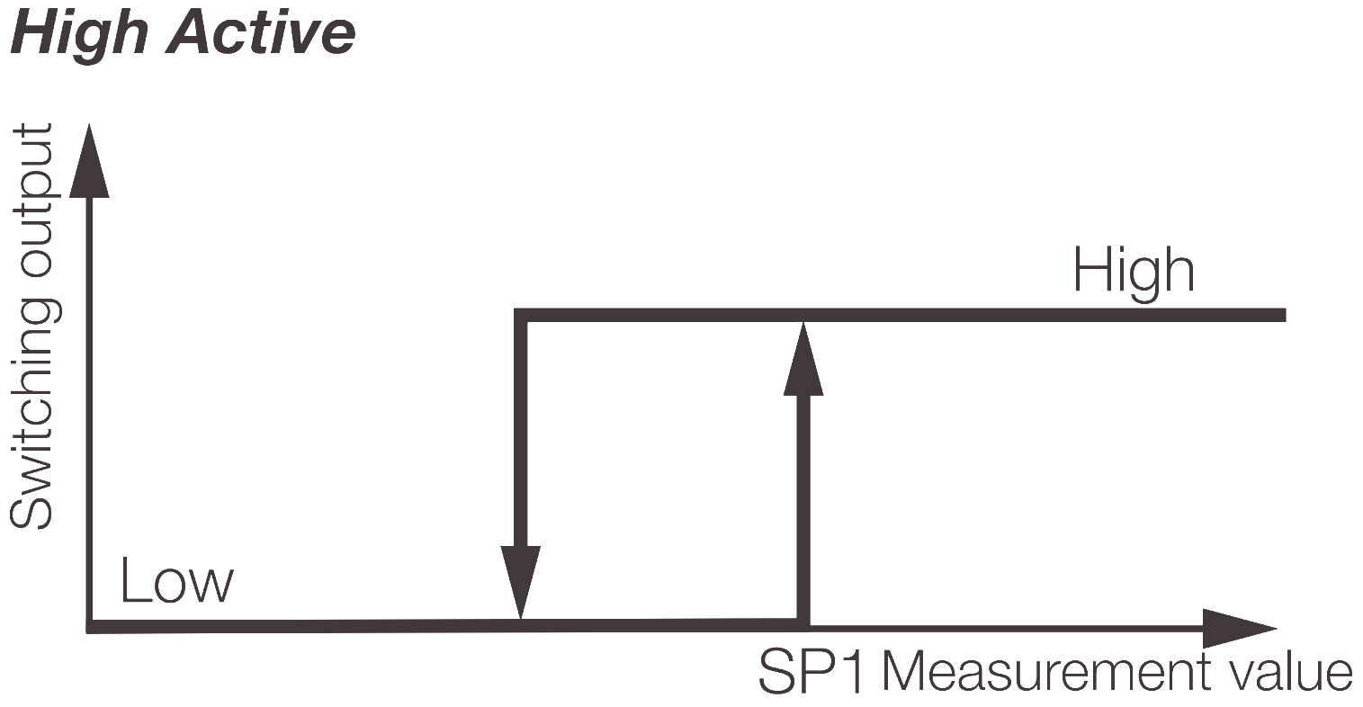
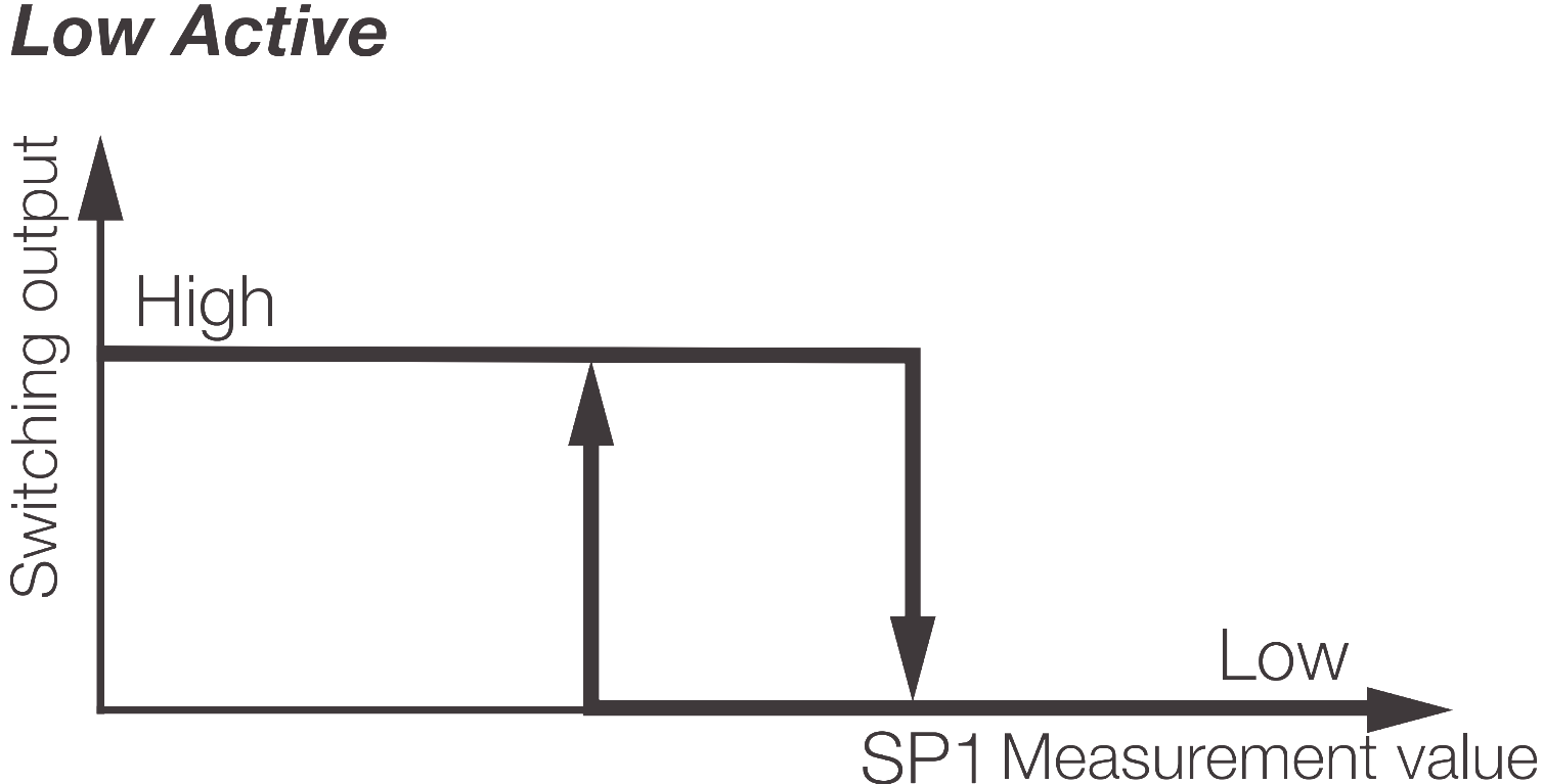
Switchpoint Logic
With switching logic High Active, the switching output switches to high if the current measurement value is greater than the set (taught) setpoint. With Low Active this logic is inverted.
 { width=”500” }
 { width=”500” }
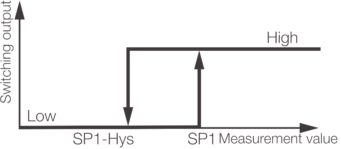
Single Point Mode
In Single Point Mode, only one switching point (setpoint) is defined.
Switching behavior:
Measurement value ≥ switching point: output active
Measurement value ≤ switching point minus a defined hysteresis: output inactive
 { width=”500” }
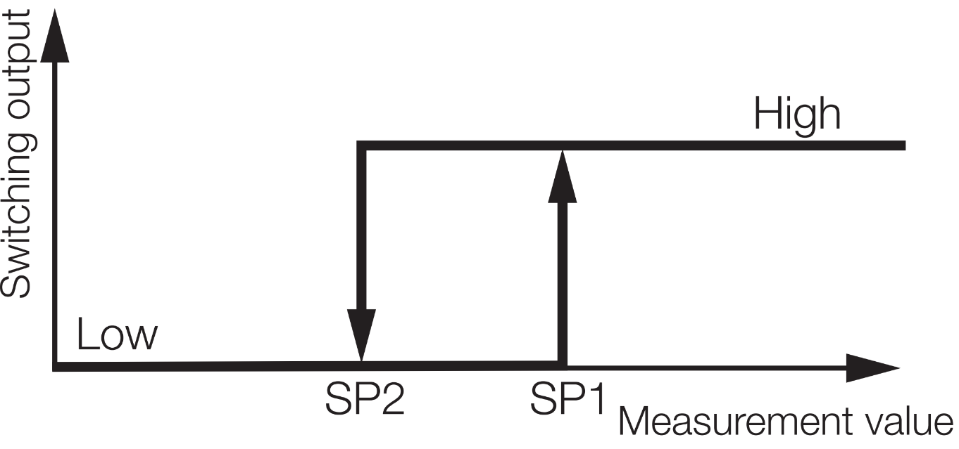
Two Point Mode
In Two Point Mode, two switching points (setpoint) are defined.
Switching behavior:
Measurement value ≥ switching point 1: output active
Measurement value ≤ switching point 2 output inactive
 { width=”500” }
Teach Process
For a successful teach-in as well to directly set a setpoint, the following conditions must be met:
The setpoint that is to be taught must be in the validity range of the measurement value signal.
Additionally in Two-Point Mode:
The distance between the setpoints must be greater than or equal to the minimum hysteresis.
An active teach process in indicated by illumination of the red LED. If the red LED flashes, the currently pending measurement value is outside of the validity range (IO-Link process) or a manual teach was not possible.
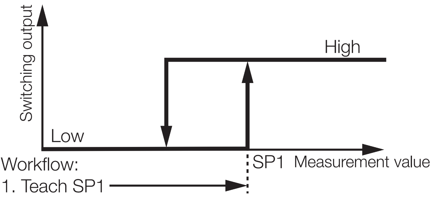
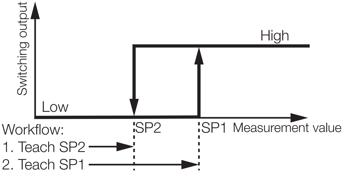
Single Value Teach
With Single-Value Teach, the switching point (setpoint) is defined via a teach point. Moreover, this is a static process, i.e., the measurement value is constant during the teach phase. The teach process is performed independently for each switching point in Two-Point Mode.
 { width=”500” }
 { width=”500” }
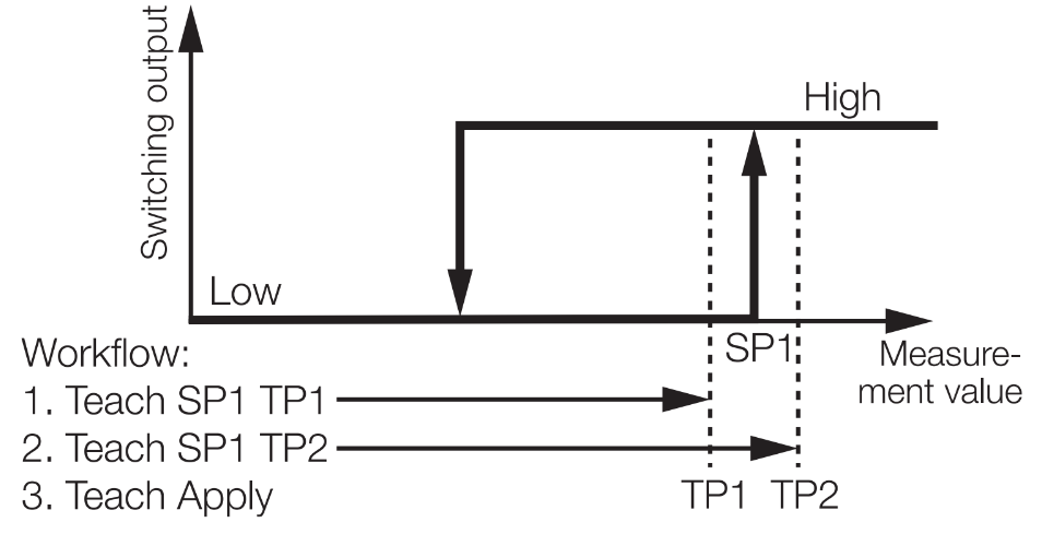
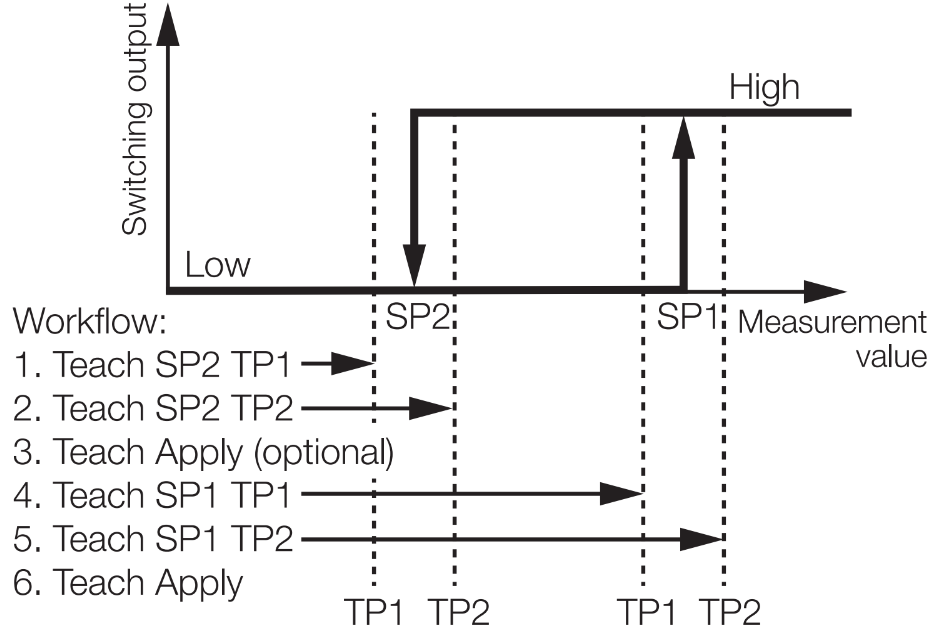
Two Value Teach
With Two-Value Teach, the switching point (setpoint) is defined via two teach points. The average value of the two teach points defines the setpoint.
This is a static process as well, i.e., each teach point is defined statically. The teach process can be performed independently for each switching point in Two-Point Mode or Window Mode.
The teach process is concluded with the Apply command; this is only possible if each of the two teach points has been taught. Alternatively, the teach process can be interrupted with a Cancel command. All incomplete teach point pairs are thereby lost.
 { width=”500” }
 { width=”500” }
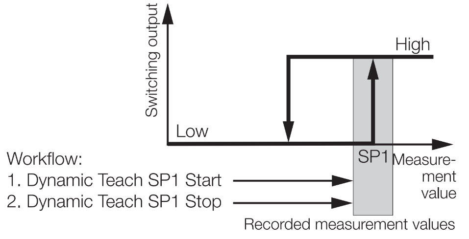
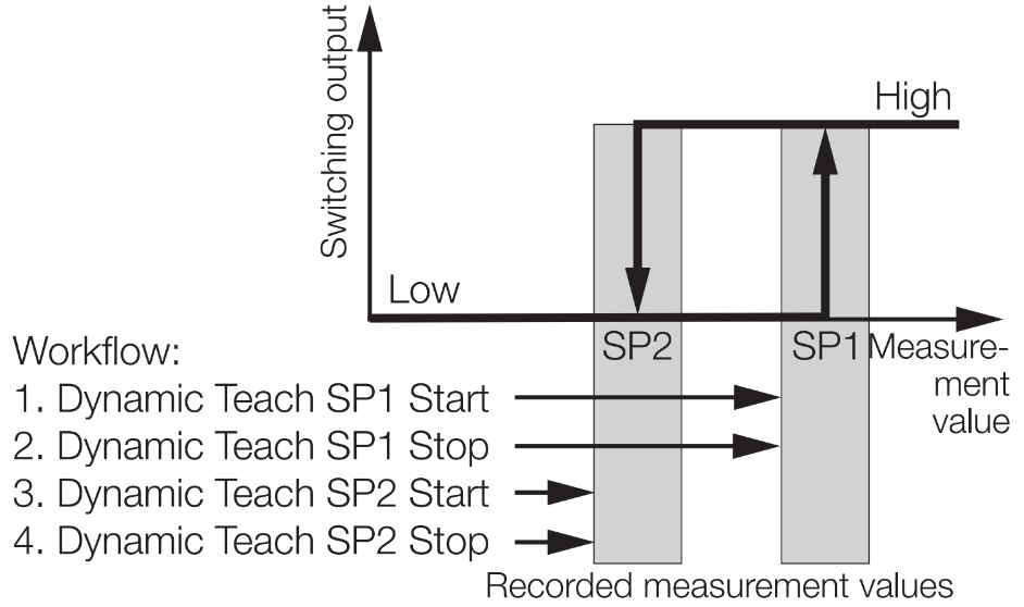
Dynamic Teach
With this process, no static teach points are recorded, unlike with the previous methods; rather, multiple measurement values are recorded over a defined period of time. Measurement value acquisition is started with the Dynamic Teach SP1 Start system command and ended with Dynamic Teach SP1 Stop. If all recorded measurement values were in the valid detection range, the switching point calculation is started. For this purpose, the minimum and maximum values are determined. The average value of these two extrema is used to form the new switching point (setpoint).
The maximum acquisition time is 5 minutes. After 5 minutes without a Stop command, the event 0x8DC0 Teach Timeout is set.
 { width=”500” }
 { width=”500” }
Process Data
| Object ID | Name | Description | Direction |
|---|---|---|---|
| 0x003F (63) | SSC 1.1 | Switching Signal Channel 1.1 | Input |
| 0x0040 (64) | SSC 1.2 | Switching Signal Channel 1.2 | Input |
| 0x0173 (371) | SSC 2.1 | Switching Signal Channel 2.1 | Input |
| 0x0174 (372) | SSC 2.2 | Switching Signal Channel 2.2 | Input |
ISDU
| Name | Index | Subindex | Access | Length | Data Type | Data Storage | Default |
|---|---|---|---|---|---|---|---|
| Teach-in Select | 0x003A (58) | 0 | R/W | 1 byte | UINT8 | No | 0x00 |
| Teach-in Result | 0x003B (59) | 0 | R | 1 byte | UINT8 | n/a | – |
| State | 1 | R | 4 bit | UINT4 | n/a | – | |
| Flag SP1 TP1 | 2 | R | 1 bit | BOOL | n/a | – | |
| Flag SP1 TP2 | 3 | R | 1 bit | BOOL | n/a | – | |
| Flag SP2 TP1 | 4 | R | 1 bit | BOOL | n/a | – | |
| Flag SP2 TP2 | 5 | R | 1 bit | BOOL | n/a | – | |
| SSC 1.1 Parameter | 0x003C (60) | 0 | R/W | 8 bytes | Yes | ||
| Setpoint 1 | 1 | R/W | 4 bytes | INT32 | 0x7FFF FFFC (deactivated) | ||
| Setpoint 2 | 2 | R/W | 4 bytes | INT32 | 0x7FFF FFFC (deactivated) | ||
| SSC 1.1 Configuration | 0x003D (61) | 0 | R/W | 4 bytes | Yes | ||
| Switchpoint Logic | 1 | R/W | 1 byte | UINT8 | 0x00 | ||
| Switchpoint Mode | 2 | R/W | 1 byte | UINT8 | 0x01 | ||
| Switchpoint Hysteresis | 3 | R/W | 2 bytes | INT16 | 10 | ||
| SSC 1.2 Parameter | 0x003E (62) |
0 | R/W | 8 bytes | Yes | ||
| Setpoint 1 | 1 | R/W | 4 bytes | INT32 | 0x7FFF FFFC (deactivated) | ||
| Setpoint 2 | 2 | R/W | 4 bytes | INT32 | 0x7FFF FFFC (deactivated) | ||
| SSC 1.2 Configuration | 0x003F (63) | 0 | R/W | 4 bytes | Yes | ||
| Switchpoint Logic | 1 | R/W | 1 byte | UINT8 | 0x00 | ||
| Switchpoint Mode | 2 | R/W | 1 byte | UINT8 | 0x01 | ||
| Switchpoint Hysteresis | 3 | R/W | 2 bytes | INT16 | 10 | ||
| SSC 2.1 Parameter | 0x400C (16396) |
0 | R/W | 8 bytes | Yes | ||
| Setpoint 1 | 1 | R/W | 4 bytes | INT32 | 0x7FFF FFFC (deactivated) | ||
| Setpoint 2 | 2 | R/W | 4 bytes | INT32 | 0x7FFF FFFC (deactivated) | ||
| SSC 2.1 Configuration | 0x400D (16397) | 0 | R/W | 4 bytes | Yes | ||
| Switchpoint Logic | 1 | R/W | 1 byte | UINT8 | 0x00 | ||
| Switchpoint Mode | 2 | R/W | 1 byte | UINT8 | 0x01 | ||
| Switchpoint Hysteresis | 3 | R/W | 2 bytes | INT16 | 10 | ||
| SSC 2.2 Parameter | 0x400E (16398) |
0 | R/W | 8 bytes | Yes | ||
| Setpoint 1 | 1 | R/W | 4 bytes | INT32 | 0x7FFF FFFC (deactivated) | ||
| Setpoint 2 | 2 | R/W | 4 bytes | INT32 | 0x7FFF FFFC (deactivated) | ||
| SSC 2.2 Configuration | 0x400F (16399) | 0 | R/W | 4 bytes | Yes | ||
| Switchpoint Logic | 1 | R/W | 1 byte | UINT8 | 0x00 | ||
| Switchpoint Mode | 2 | R/W | 1 byte | UINT8 | 0x01 | ||
| Switchpoint Hysteresis | 3 | R/W | 2 bytes | INT16 | 10 |
Teach in Select
With the help of this parameter, the switching channel that is to be taught is selected.
| Value | Meaning | Description |
|---|---|---|
| 0 | Default SSC | SSC1.1 |
| 1 | SSC 1.1 | |
| 2 | SSC 1.2 | |
| 11 | SSC 2.1 | |
| 12 | SSC 2.2 |
Teach in Result
Outputs the current status of the currently active or of the last teach-in process:
| Teach in Flags SP | Teach in State | ||||||
|---|---|---|---|---|---|---|---|
| SP2 | SP1 | ||||||
| TP2 | TP1 | TP2 | TP1 | ||||
| Bit 7 | Bit 0 | ||||||
| Bit position |
Meaning | Description |
|---|---|---|
| 7 | Flag SP2 TP2 | 0 = Teach point not detected or not successfully detected. 1 = Teach point successfully detected. |
| 6 | Flag SP2 TP1 | |
| 5 | Flag SP1 TP2 | |
| 4 | Flag SP1 TP1 | |
| 3…0 | State | 0 = IDLE – No currently active teach process 1 = SUCCESS – SP1 teach was successful. 2 = SUCCESS – SP2 teach was successful. 3 = SUCCESS – SP1 and SP2 teach was successful. 4 = WAIT FOR COMMAND – Wait for next command. 5 = BUSY – Process active 6 = Reserved 7 = ERROR – Last process was not successful. |
SSC Parameter
This parameter represents the currently configured switching points for each switching channel (setpoint 1 and setpoint 2). The switching point 1 (setpoint 1) is active in all switching modes and can be taught. Switching point 2 (setpoint 2) is only active in Two-Point or Window Mode and is otherwise deactivated.
It is possible to deactivate a switching channel (SSC) by assigning the value 0x7FFFFFFC (Setpoint not teached) to one of the active setpoints.
SSC Configuration
This parameter is used to configure the SSC. It is possible to set the switching logic, switching mode as well as the hysteresis.
If the switching mode is changed, the setting of the setpoint parameter can be adjusted:
If changing from Two-Point or Window Mode to Single-Point Mode, setpoint 2 is set to 0x7FFFFFFC and thereby deactivated. In this state or in this setting, the setting of setpoint 2 cannot take on any other value.
If changing from Single-Point Mode to Two-Point oder Window Mode, setpoint 2 is again activated and set to the value of setpoint 1 minus the minimum hysteresis and, in the subsequent process, can be taught to a different value.
| Value | Meaning | Description |
|---|---|---|
| Switchpoint Logic | ||
| 0x00 (0) | High Active | |
| 0x01 (1) | Low Active | |
| Switchpoint Mode | ||
| 0x00 (0) | Deactivated | Switching channel deactivated |
| 0x01 (1) | Single Point | Single-Point Mode (SP1 activated) |
| 0x02 (2) | Window | Window Mode (SP1 + SP2 activated) |
| 0x03 (3) | Two Point | Two-Point Mode (SP1 + SP2 activated) |
| Switchpoint Hysteresis | ||
| 0x0032…0x03E8 (0…1000) | – Minimum: 0 (0x0000) – Maximum: 1000 (0x03E8) – Default: 10 (0x000A) The hysteresis is used as an integer offset to the switching point value. |
|
System Commands
| Command Value | Device Action |
|---|---|
| 0x40 (64) | Teach Apply – Calculates the switching point for SP1, SP2. |
| 0x41 (65) | Teach SP – Determines teach point 1 for the setpoint and calculates the switching point. |
| 0x41 (65) | Teach SP1 – Determines teach point 1 for setpoint 1 and calculates the switching point. |
| 0x42 (66) | Teach SP2 – Determines teach point 1 for setpoint 2 and calculates the switching point. |
| 0x43 (67) | Teach SP TP1 – Determines teach point 1 for the setpoint 1. |
| 0x44 (68) | Teach SP TP2 – Determines teach point 2 for the setpoint 1. |
| 0x45 (69) | Teach SP2 TP1 – Determines teach point 1 for setpoint 2. |
| 0x46 (70) | Teach SP2 TP2 – Determines teach point 2 for setpoint 2. |
| 0x47 (71) | Teach SP1 Start – Starts dynamic teach-in for setpoint 1 |
| 0x48 (72) | Teach SP1 Stop – Stops dynamic teach-in for the setpoint and calculates the switching point. |
| 0x49 (73) | Teach SP2 Start – Starts dynamic teach-in for setpoint 2 |
| 0x4A (74) | Teach SP2 Stop – Stops dynamic teach-in for setpoint 2 and calculates the switching point. |
| 0x4E (78) | Teach Reset – The teach-in process is interrupted, the setpoints are reset to the default settings. |
| 0x4F (79) | Teach Cancel – The teach-in process is interrupted. |
For an overview of all System Commands, see section System commands.
Events
| Event Code | Event Type | Event – Description - Remedy | Device Status |
|---|---|---|---|
| 0x8DC0 (36288) |
Notification | Dynamic Teach-in Timeout – The current teach-in process took too long and was interrupted. ► The teach-in process must be completed within 5 minutes. |
0 – Device is operating properly. |