Measurement Profiles
Description
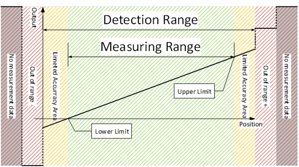
The sensor realizes the measuring Smart Sensor Profile Ed. 2 according to profile SSP 4.2.2. The profile defines four different ranges in which a measurement value (Measurement Value) can be output:
The measurement range (Measurement Range)
Detection range (Detection Range)
Out of Range
No Measurement Data
The evaluation is realized based on the value “Transducer Value High Resolution” (PDObjectID 0x0025) as the distance output provided by the Radar Frontend, see Radar Frontend.
 { width=”500” }
Measurement Range
Within the measurement range, all values specified in the data sheet related to measurement accuracy are satisfied. Information on the size of the measurement range can be found in parameter MDC Descriptor, which contains the lower measurement limit (Lower Limit) and upper measurement limit (Upper Limit).
Detection Range
Outside of the measurement range, a measurement value output in the non-linear areas (Limited Accuracy Areas) is still possible, though the accuracy cannot be ensured for these areas. Limited accuracy is indicated via the Measurement Warning bit in the process data.
Out of Range
Outside of the detection range, the sensor can determine whether the measurement value is below or above the detection range. A meaningful measurement value is not possible in these areas. Instead, a replacement value is output:
| Status | Value |
|---|---|
| Out of Range Minus | –2,147,483,640 (0x80000008) |
| Out of Range Plus | 2,147,483,640 (0x7FFFFFF8) |
In addition to the replacement value, the Measurement Error bit is set.
No Measurement Data
If no measurement value can be determined, the replacement value No Measurement Data is output:
| Status | Value |
|---|---|
| No Measurement Data |
2,147,483,644 (0x7FFFFFFC) |
In addition to the replacement value, the Measurement Error bit is set.
This state is set if no target can be detected within the measurement range. See more details in Radar Frontend.
Process Data
| Object ID | Name | Description | Direction |
|---|---|---|---|
| 0x0028 (40) | Measurement Value (Distance) | Distance measurement value. | Input |
| 0x002A (42) | Measurement Scale (Distance) | The scaling as the exponent of a power of ten | Input |
| 0x002B (43) | Measurement Error | Measurement value outside of the detection range or no measurement value | Input |
| 0x002C (44) | Measurement Warning | Measurement value outside of the measurement range | Input |
| 0x0171 (369) | Measurement Value (Target Strength) | Target Strength value. | Input |
| 0x0172 (370) | Measurement Scale (Target Strength) | The scaling as the exponent of a power of ten | Input |
Measurement Value
The current measurement value as signed, 32-bit number. In case of an error, a substitute value is output (see Out of range and No measurement data).
Measurement Scale
The scaling value is a signed, 8-bit number. The scaling indicates the exponents of a power of ten of the measurement value relative to the base unit meter in case of Distance, and dB in case of Target Strength. This value is used to interpret the unit of the output value.
Measurement Error
Indicates if the measurement value is outside of the detection range or if no measurement value can be determined.
Measurement Warning
Indicates if the measurement value is outside of the measurement range.
Process Data Profiles
PDin
| Process Data | |||||||||||
|---|---|---|---|---|---|---|---|---|---|---|---|
| Byte 11 | Byte 10 | Byte 9 | Byte 8 | Byte 7 | Byte 6 | Byte 5 | Byte 4 | Byte 3 | Byte 2 | Byte 1 | Byte 0 |
| MDC1 (Target Distance) | MDC1 Scale | Status and Switching Signal Channels | MDC2 (Target Strength) | MDC2 Scale | Switching Signal Channels | ||||||
| Status and Switching Signal Channels | |||||||
|---|---|---|---|---|---|---|---|
| Bit 7 | Bit 6 | Bit 5 | Bit 4 | Bit 3 | Bit 2 | Bit 1 | Bit 0 |
| System error | Measurement Error | Measurement range warning | Signal Quality [^1] | Switching Signal Channel 1.2 | Switching Signal Channel 1.1 | ||
| Switching Signal Channels | |||||||
|---|---|---|---|---|---|---|---|
| Bit 7 | Bit 6 | Bit 5 | Bit 4 | Bit 3 | Bit 2 | Bit 1 | Bit 0 |
| Switching Signal Channel 2.2 | Switching Signal Channel 2.1 | ||||||
ISDU and Reset Behavior
| Name | Index | Subindex | Access | Length | Data Type | Data Storage | Default |
|---|---|---|---|---|---|---|---|
| Measurement Data Channel Descriptors | |||||||
| MDC1 Descriptor | 0x4080 (16512) | 0 | R | 11 bytes | n/a | ||
| Lower Limit | 1 | R | 4 bytes | INT32 | n/a | 300 | |
| Upper Limit | 2 | R | 4 bytes | INT32 | n/a | 15000 | |
| Unit Code | 3 | R | 2 bytes | UINT16(ENUM) | n/a | 1010 (m) | |
| Scale | 4 | R | 1 byte | INT8 | n/a | -3 | |
| MDC2 Descriptor | 0x4081 (16513) | 0 | R | 11 bytes | n/a | ||
| Lower Limit | 1 | R | 4 bytes | INT32 | n/a | 0 | |
| Upper Limit | 2 | R | 4 bytes | INT32 | n/a | 64 | |
| Unit Code | 3 | R | 2 bytes | UINT16(ENUM) | n/a | 1383 (dB) | |
| Scale | 4 | R | 1 byte | INT8 | n/a | 0 | |
| Measurement Channel configuration (only for Distance measurement value) | |||||||
| Hide Limited Accuracy Areas | 0x00C0 (192) | 0 | R/W | 1 byte | UINT8(ENUM) | Yes | 0 |
| Measurement Offset | 0x00C1 (193) |
0 | R/W | 4 bytes | INT32 | Yes | 0 |
| Measurement Preset | 0x00C2 (194) |
0 | R/W | 4 bytes | INT32 | Yes | 0 |
| Measurement Output Characteristics | 0x00C3 (195) |
0 | R/W | 1 byte | BOOL | Yes | 0 |
| Measurement Hysteresis | 0x00C4 (196) | 0 | R/W | 4 bytes | UINT32 | Yes | 0 |
| Measurement Range | 0x0202 (514) | 0 | R/W | 8 bytes | Yes | ||
| Lower Limit | 1 | R/W | 4 bytes | INT32 | 300 mm | ||
| Upper Limit | 2 | R/W | 4 bytes | INT32 | 15000 mm | ||
MDC Descriptor
The MDC Descriptor contains information about the current value range of the measurement value (Measurement Value) within the limits of the measurement range (Measurement Range), about the unit and the scaling of the measurement value. The values for the lower measurement limit (Lower Limit) and upper measurement limit (Upper Limit) specify the value range.
The Scale parameter in the MDC Descriptor is a signed 8 bit number. The scaling indicates the exponents of a power of ten of the measurement value relative to the base unit. The basic unit is coded by the parameter Unit Code in the MDC Descriptor. The possible unit values of the sensor include:
| Unit | Value |
|---|---|
| Meter | 1010 |
| Decibel | 1383 |
On delivery, the lower measurement value limit has its origin at value 300. If an offset is set, the value of the lower measurement value limit changes according to the Measurement Offset.
Hide Limited Accuracy Areas
Measurement values are still displayed outside the measuring range. These do not conform to the limits specified in the data sheet. The output of the non-linear area (Limited Accuracy Areas) can be configured. If the output is deactivated (Hidden), the sensor outputs either Out Of Range Plus or Out Of Range Minus if the measurement range is exited.
| Value | Meaning |
|---|---|
| 0x00 (0) | Visible |
| 0xFF (255) | Hidden |
Measurement Offset
The Measurement Offset is subtracted from the current measurement value. This parameter can be reset using Application Reset and Factory Reset.
Measurement Preset
Measurement Preset can be used to calculate a Measurement Offset. Measurement Preset specifies a target value that should be achieved after a Teach Preset by the current measurement value. Following a successful Teach Preset, the current measurement value has the same value as Measurement Preset.
This parameter can be reset using Application Reset and Factory Reset.
Measurement Output Characteristics
The Measurement Output Characteristics parameter defines the output characteristic, which can be rising or falling. This setting affects the offset setting. It is possible that the offset setting needs to be performed again after this setting is changed.
This parameter can be reset using Application Reset and Factory Reset.
| Value | Meaning |
|---|---|
| 0x00 (0) | Falling |
| 0xFF (255) | Rising |
Measurement Hysteresis
The hysteresis of the measurement value can be set with parameter Measurement Hysteresis. This parameter is used to dampen unstable measurement values. This parameter can be reset using Application Reset and Factory Reset.
Measurement Range
With Measurement Range, the measurement range can be changed by teaching with the Teach Lower Limit and Teach Upper Limit System Commands or by overwriting the parameter.
This parameter Measurement Range can be reset using Application Reset and Factory Reset.
System Commands
| Command Value | Device Action |
|---|---|
| 0xE0 (224) | Teach Preset – Sets the current measurement value to the value of Measurement Preset. |
| 0xE1 (225) | Teach Lower Limit – Sets the lower end of the measurement range. |
| 0xE2 (226) | Teach Upper Limit – Sets the upper end of the measurement range. |
For an overview of all System Commands, see section System commands.
Events
| Event Code | Event Type | Event – Description – Remedy | Device Status |
|---|---|---|---|
| 0x8D00 (36096) | Warning | The measurement value is below the measure ment range. Accuracy cannot be guaranteed. |
2 – Out of Specification |
| 0x8D01 (36097) | Warning | The measurement value is above the measure ment range. Accuracy cannot be guaranteed. |
2 – Out of Specification |
| 0x8D02 (36098) | Warning | The measurement value is below the detection range; no measurement value can be determined. ► Check application. |
2 – Out of Specification |
| 0x8D03 (36099) | Warning | The measurement value is above the detection range; no measurement value can be determined. ► Check application. |
2 – Out of Specification |
| 0x8D04 (36100) | Warning | No measurement value can be determined. ► Check application. |
2 – Out of Specification |
| 0x8D05 (36101) | Warning | Measurement error/redundancy check failed. ► Check application. |
2 – Out of Specification |