Digital Output#
Chapter goal
Goal: Output a detected object via a digital output.
Prerequisite
The configuration and monitoring tool (CMTK) is used here only for parameterization – it can display the state of pin 2 and 4 but cannot record or further process it.
How it works#
The sensor can output two switching channels via digital outputs. These share pins with analog output and IO-Link – you must decide on usage.
Parameters are summarized in the following table.
Use of IO-Link pin
The IO-Link pin automatically detects an IO-Link master, activates IO-Link and disables the digital output. This behavior cannot be overridden.
Parameter table
ParameterSectionParameter name |
IndexSubindex |
Default |
|---|---|---|
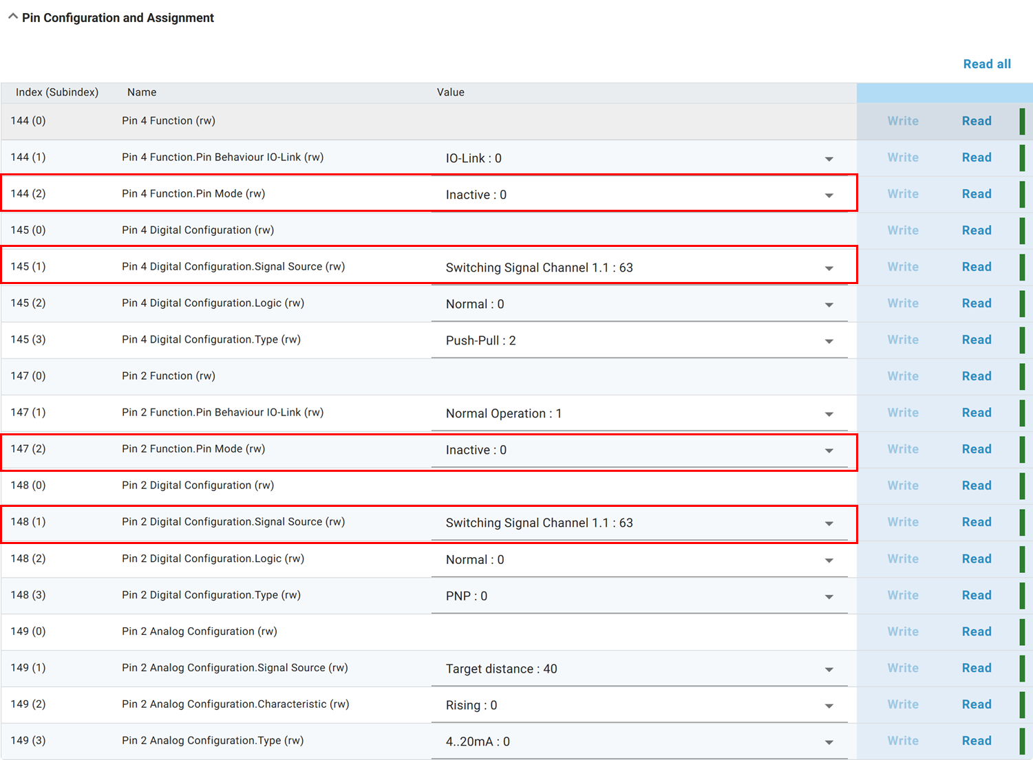
Pin 4 modePin Configuration and AssignmentPin 4 Function.Pin Mode |
1442 |
Inactive |
Pin 4 signal sourcePin Configuration and AssignmentPin 4 Digital Configuration.Signal Source |
1451 |
Switching Signal Channel 1.1 |
Pin 2 modePin Configuration and AssignmentPin 2 Function.Pin Mode |
1472 |
Inactive |
Pin 2 signal sourcePin Configuration and AssignmentPin 2 Digital Configuration.Signal Source |
1481 |
Switching Signal Channel 1.1 |
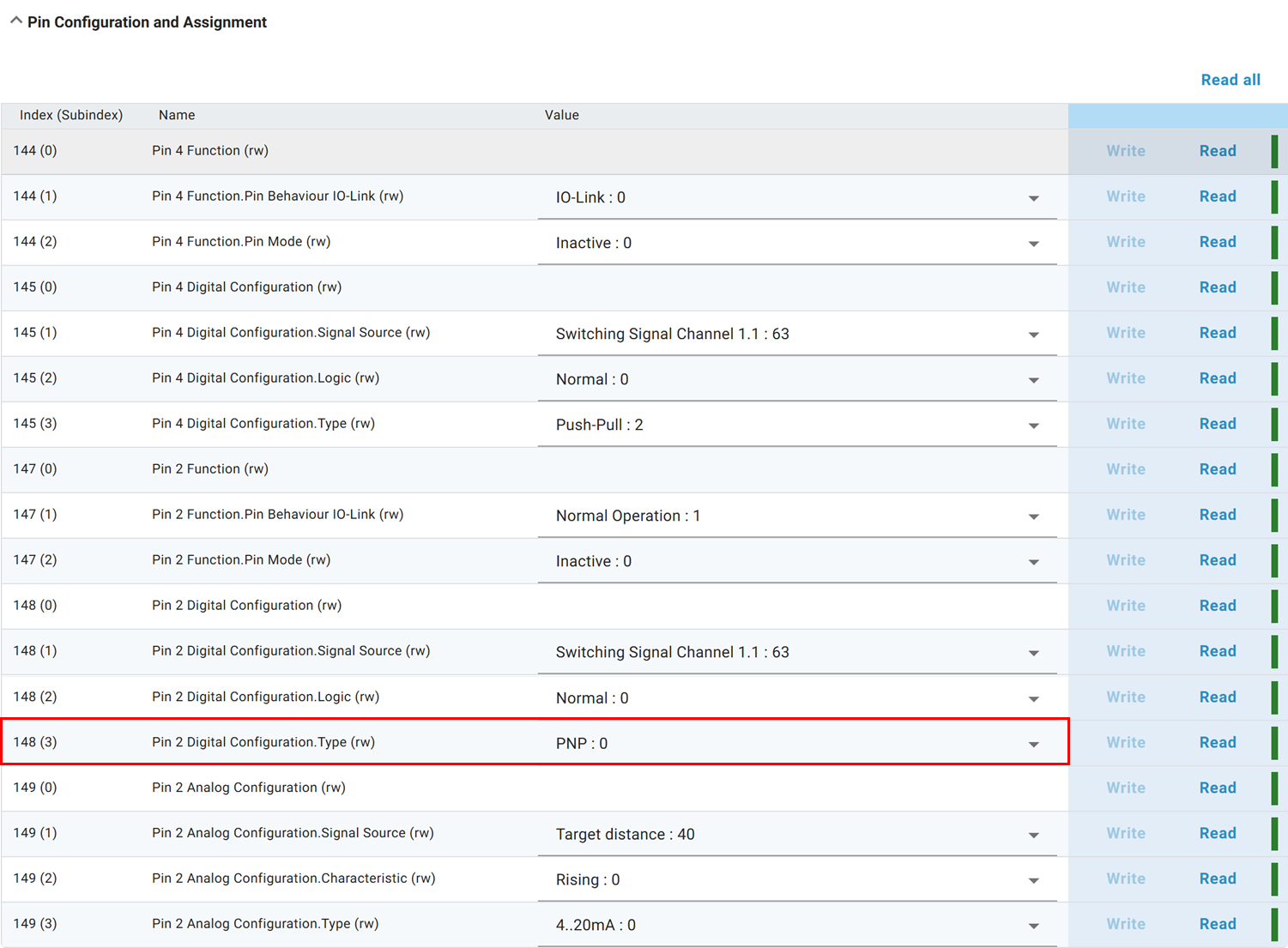
Pin 2 typePin Configuration and AssignmentPin 2 Digital Configuration.Type |
1483 |
PNP |
Pin assignment

| PIN | Function |
|---|---|
| 1 | 24 V |
| 2 | Digital output / Analog output |
| 3 | 0 V |
| 4 | IO-Link / Digital output |
Configuration#
1. Configure object detection#
First set up object detection – alternatively you can output certain system states.
Possible output signals
| Description | Name | Value |
|---|---|---|
| Switching channel 1.1 | Switching Signal Channel 1.1 | 63 |
| Switching channel 1.2 | Switching Signal Channel 1.2 | 64 |
| Switching channel 2.1 | Switching Signal Channel 2.1 | 371 |
| Switching channel 2.2 | Switching Signal Channel 2.2 | 372 |
| Supply voltage warning - under-voltage | Primary supply voltage under-run | 23 |
| Supply voltage warning - over-voltage | Primary supply voltage over-run | 24 |
| Error state - No object in detection range | MDC Measurement Error | 43 |
| Measurement range warning | MDC Out of Measurement Range Warning | 44 |
| System error | System Error | 47 |
| Temperature alarm | Device Temperatur Alarm-Status | 78 |
2. Configure pin mode and signal source#
Set pin mode to Digital Output and choose the desired switching channel as signal source. The pin configuration settings are under Pin Configuration and Assignment.
3. Configure switching type#
Pin 4 supports only Push-Pull. Pin 2 supports PNP, NPN or Push-Pull.
Switching types
PNP: Load connection to +24 V, output switches against 0 V.
NPN: Load connection to 0 V, output switches against +24 V.
Push-Pull: Can actively switch against +24 V or 0 V (compatible to PNP and NPN).
- Next section
Step 6 – Radar Reflex Gate mode – Near-range object detection