Radar Reflex Gate Mode
Chapter goal
Goal: Understand the Radar Reflex Gate mode and configure it correctly for near-range object detection.
Prerequisite
Basic commissioning and IO-Link connection are completed (see Connection & Commissioning).
The CMTK is used for parameterization.
Besides distance measurement the sensor offers the Radar Reflex Gate mode. It is optimized for near-range object detection and uses a different algorithm.
How it works
The mode uses differences in reflection strength between materials. Instead of continuously determining distance, the sensor observes magnitude at a reference distance (reflector). A strong reflector (e.g. a metal plate) produces a high peak. If an object intrudes between sensor and reflector, magnitude changes – usually decreases, sometimes increases (material / geometry).
You can visualize the principle in the Radar Sensor UI.
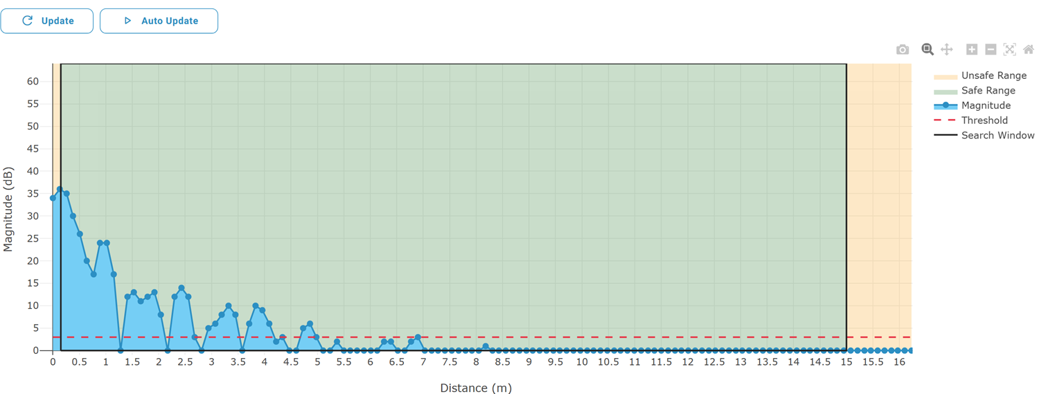
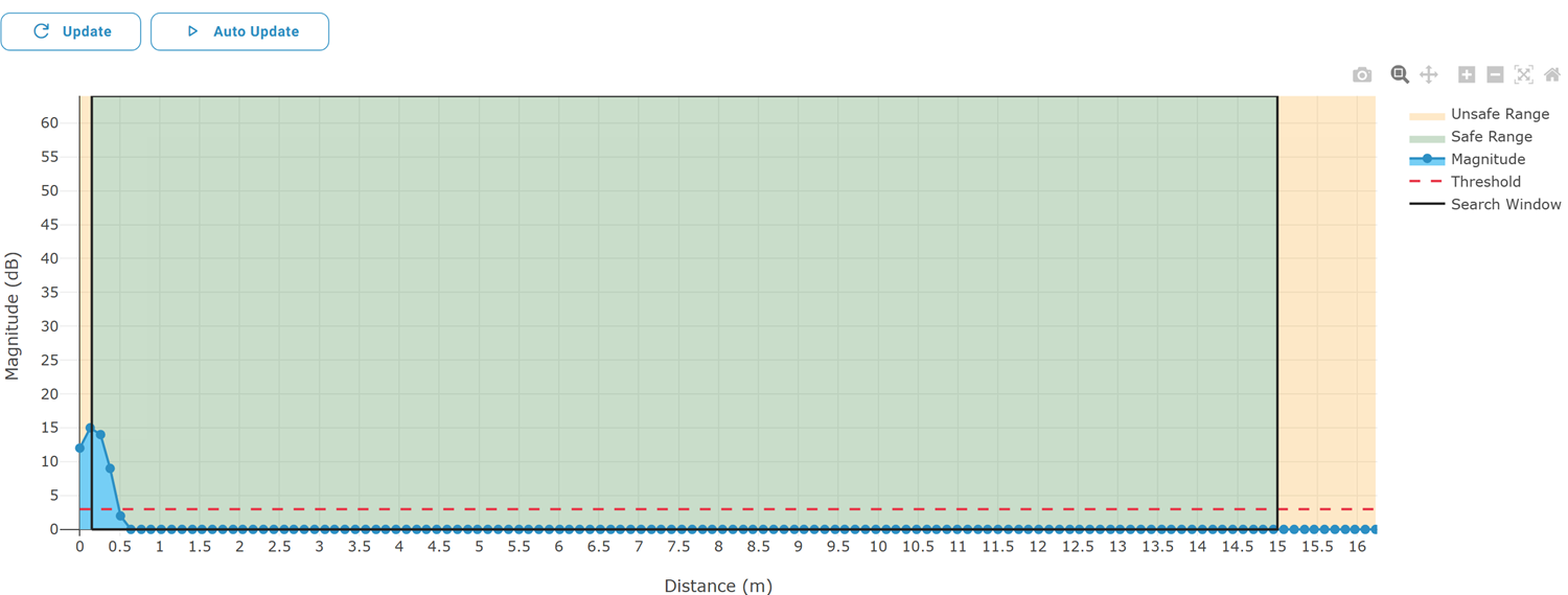
Here a metal plate is mounted in the immediate vicinity (~10 cm). The distance display does not need to show exactly 10 cm – in this mode exact distance is secondary. When, for example, a hand is placed between the sensor and the reflector, the peak drops (e.g. from ~40 dB to ~20 dB).
Info
Magnitude is given in dB (logarithmic). A difference of −3 dB corresponds roughly to halving the power.
Note
Process data remains structurally unchanged. Distance is updated only roughly every 10 seconds and serves merely for orientation of peak position. Magnitude shows exclusively the value at reflector distance.
Parameter table
Configuration
1. Change variant
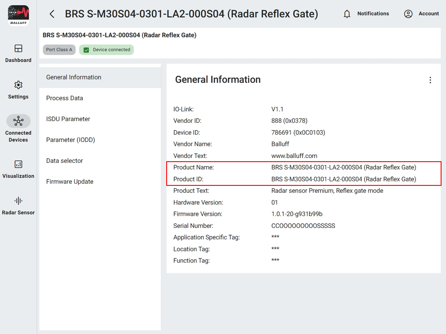
Activate the mode via variant configuration under Variant Configuration.

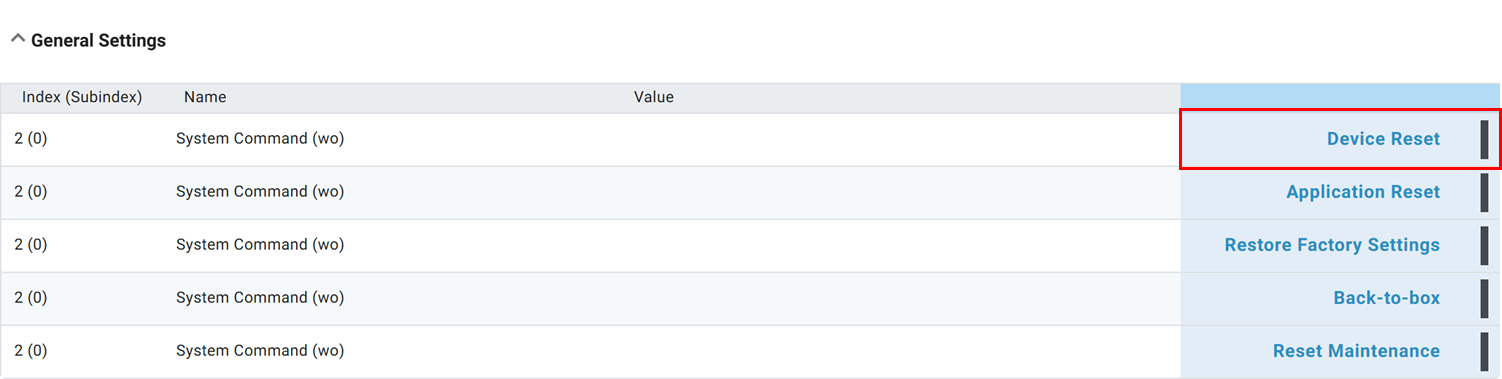
The setting becomes effective only after a restart (disconnect the connector or perform a device reset (Device Reset) under General Settings).
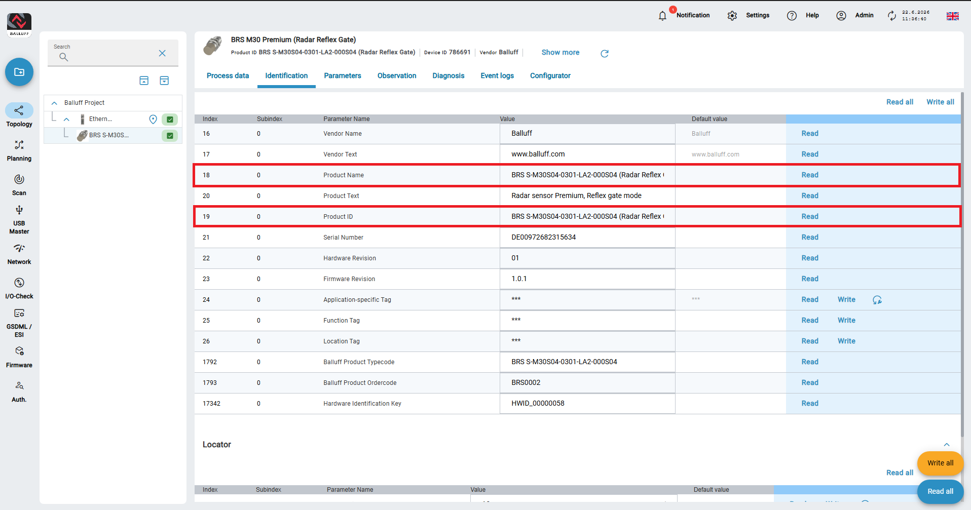
After restart, the sensor reports the variant Radar Reflex Gate. If the IODD is missing you must upload it (see Commissioning).
2. Teach reflector
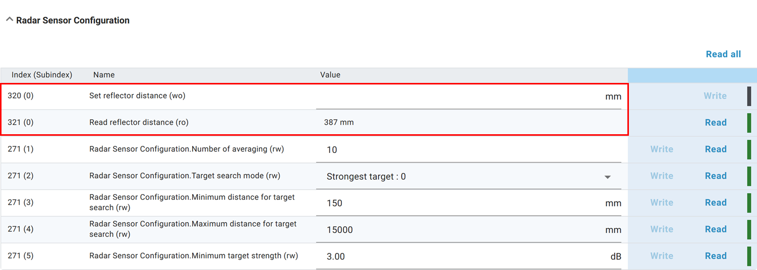
You find the reflector settings under Radar Sensor Configuration. Enter the measured or process-data derived distance under Set reflector distance. The sensor searches around this value for the strongest peak and sets it as reference. Verify with Read reflector distance.
Tip
The mode is usable without reflector if the target itself reflects strongly. Then teach the object directly and evaluate changes of magnitude.
3. Configure switching channel
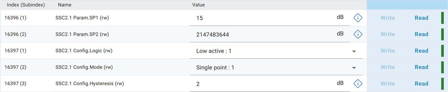
Configure a switching channel. Only variants 2.1 or 2.2 (magnitude) make sense. Hysteresis should typically be less than 10 dB.
In most cases an object is considered detected when magnitude is lower than the reflector/reference magnitude. You can therefore invert switching logic. A possible configuration is shown below.
Optionally route the switching channel to a Digital Output.
Tip
The temporal course of magnitude can provide additional information, e.g. edge profiles of passing objects or material differences. For analysis, output magnitude on the Analog Output (1 kHz update) and record it.