Object Detection
Chapter goal
Goal: Detect an object in the measurement range and output it via IO-Link.
Four switching channels are available for object detection: two switch on distance, two on magnitude. Channel parameters are summarized below.
Key Terms
How it works
Object detection continuously compares a measured value with a defined switching point and triggers a switching signal when the measurement exceeds the threshold or falls below it.
There are four switching channels: two for distance, two for magnitude. The sensor compares the current measured value with these switching values and changes its state according to the selected mode (Single Point, Two Point, Window Mode). Detailed configuration and parameter tables follow in the next section.
Parameter table – Switching Signal Channel 1.1 (Distance)
Parameter table – Switching Signal Channel 1.2 (Distance)
Parameter table – Switching Signal Channel 2.1 (Magnitude)
Parameter table – Switching Signal Channel 2.2 (Magnitude)
Note
All four switching channels are configured identically. The only difference is the input value (distance or magnitude). Examples refer to Switching Signal Channel 1.1.
Configuration
1. Configure switching mode
Choose a switching mode (three options):
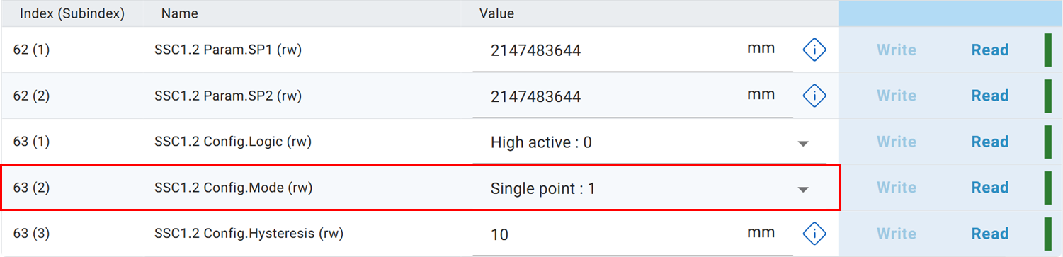
Details on how the modes work can be expanded here.
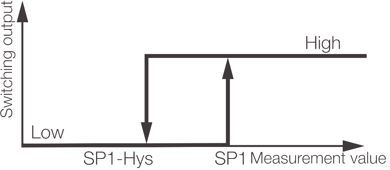
Single Point
Single Point uses only SP1 and optionally hysteresis. The channel becomes active when the measurement is greater than or equal to SP1 and only returns to inactive when the measurement falls below SP1 minus the configured hysteresis.
Example: SP1 = 1000 mm, Hysteresis = 10 mm → ON at ≥ 1000 mm, OFF at < 990 mm.
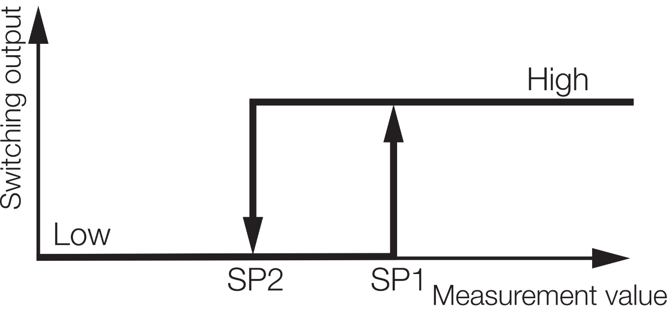
Two Point
Two Point uses SP1 and SP2 and does not use hysteresis. The channel turns ON when the measurement ≥ SP1 and turns OFF when the measurement < SP2.
Example: SP1 = 1200 mm, SP2 = 1100 mm → ON at ≥ 1200 mm, OFF at < 1100 mm.
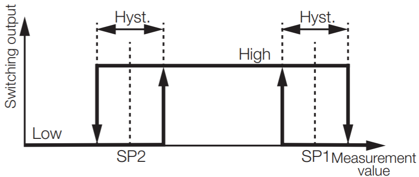
Window Mode
Window Mode is active only when the measurement lies between SP1 and SP2. Hysteresis is applied to both edges (50% split of the configured hysteresis value).
Example: SP1 = 800 mm, SP2 = 1200 mm, Hysteresis = 40 mm → nominal active window 800–1200 mm. A change beyond ±20 mm at an edge is required to flip the state.
2. Configure hysteresis
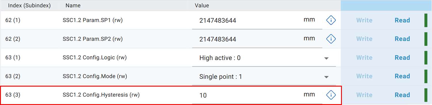
Hysteresis is effective only in Single Point and Window Mode. A value of 0 disables it. Two Point mode does not use hysteresis.
What is Hysteresis and why do I need it?
Hysteresis is a dead band around a switching point that ignores small fluctuations in the measured value so the output does not chatter. Without hysteresis, measurement noise around the threshold can cause rapid ON/OFF toggling that stresses relays, creates false events and complicates downstream logic. Example: with SP1 = 1000 mm and Hysteresis = 10 mm, measurements between 995 mm and 1005 mm will not flip the output. A sustained change beyond 10 mm is required. Practical guidance: distance channels commonly use 5–20 mm hysteresis. Magnitude channels typically need smaller hysteresis (for example 2–5 dB). Setting hysteresis to 0 disables it.
Note
Default: 10 mm / 10 dB. For magnitude channels (2.1 / 2.2) a smaller hysteresis is usually required.
3. Configure switching points
Important
Switching points are not identical to switching channels. A channel uses one or two switching points depending on mode.
You can configure a channel’s switching points manually or teach them via the Teach function.
Manual: Enter values in SP1 / SP2. Value 2147483644 disables the channel. Unused points do not need resetting.
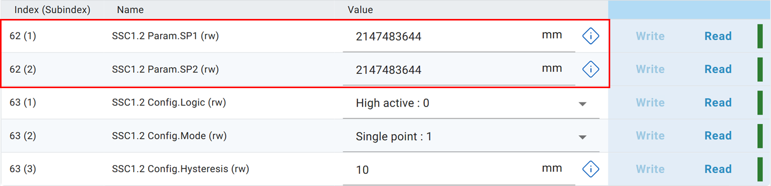
“Teach” captures the sensor’s current measurement and stores it as a switching point. There are three teach modes: Single Value, Two Value, Dynamic. Only Single Value is covered here. Information on the other modes is in the IO-Link configuration guide.
Note
Two Value Teach is not identical to Two Point. All switching modes work with all teach modes.
Parameter table – Single Point Teach
First select the channel to teach. Teach SP1 / Teach SP2 sets the current value for SP1 or SP2, respectively.
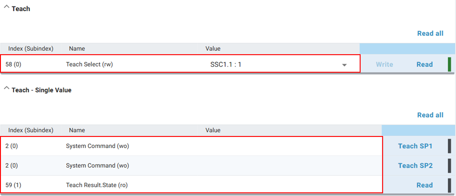
Use Teach Result to check status. An error occurs e.g. if no target is detected.
Value |
Meaning |
|---|---|
0 |
Idle |
1 |
Switching point 1 taught successfully |
2 |
Switching point 2 taught successfully |
7 |
Error during teaching |
4. Invert switching behavior
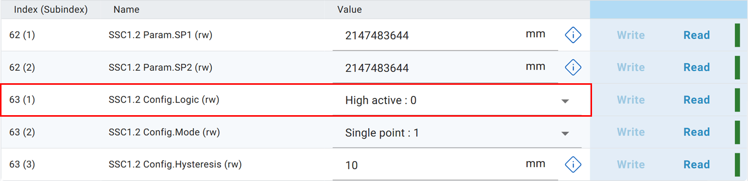
With the parameter Logic you invert behavior (High active / Low active).
My switching behavior in the near range is not reliable
Below 500 mm distance and magnitude values can fluctuate. For the near range use the Radar Reflex Gate mode.
Step 5 – Output detected object via a digital output