Analog Output
Chapter goal
Goal: Output distance or magnitude via the analog output.
Prerequisite
The CMTK here is only for parameterization – for measuring or checking a current/voltage value or switching level you must connect the sensor to suitable evaluation or control equipment (e.g. PLC, measuring device).
How it works
The sensor can output the measured distance or magnitude via the analog output at Pin 2 as a voltage or current signal. The parameter tables below give an overview of the relevant settings.
Parameter table
Pin assignment

PIN |
Function |
|---|---|
1 |
24 V |
2 |
Digital output / Analog output |
3 |
0 V |
4 |
IO-Link / Digital output |
Configuration
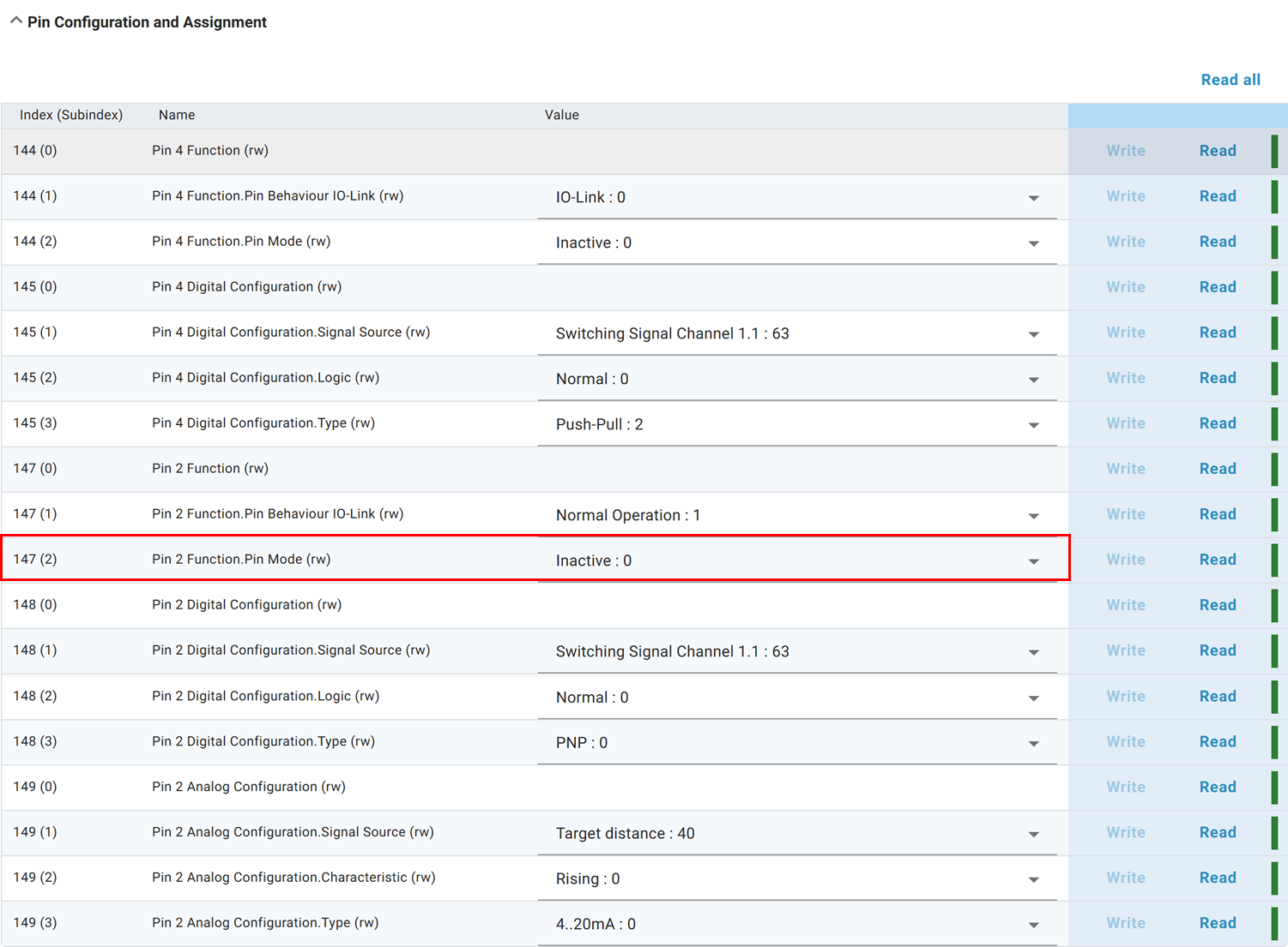
1. Activate analog output
Set Pin‑2 mode to Analog Output. You can find the pin configuration under Pin Configuration and Assignment. By default, the pin outputs distance as a current value (4–20 mA).
2. Configure signal source
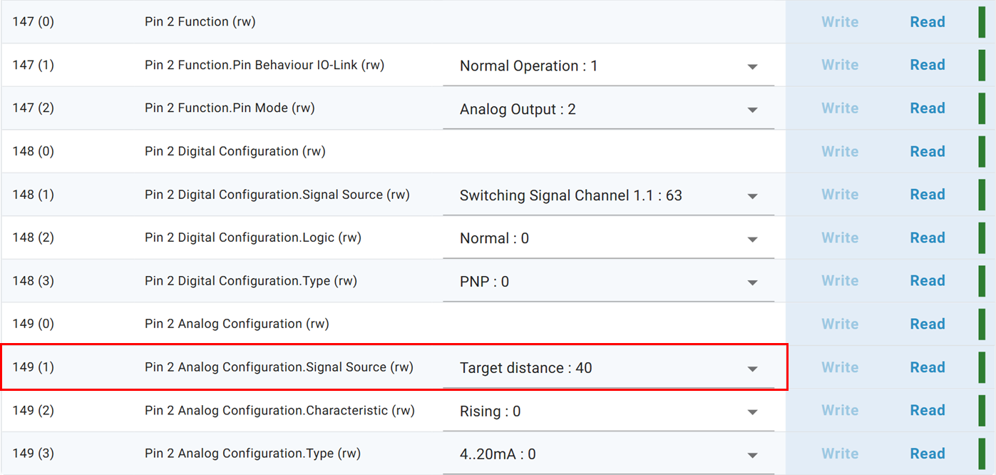
You can choose either distance (Target Distance) or magnitude (Target Strength) as signal source.
Info
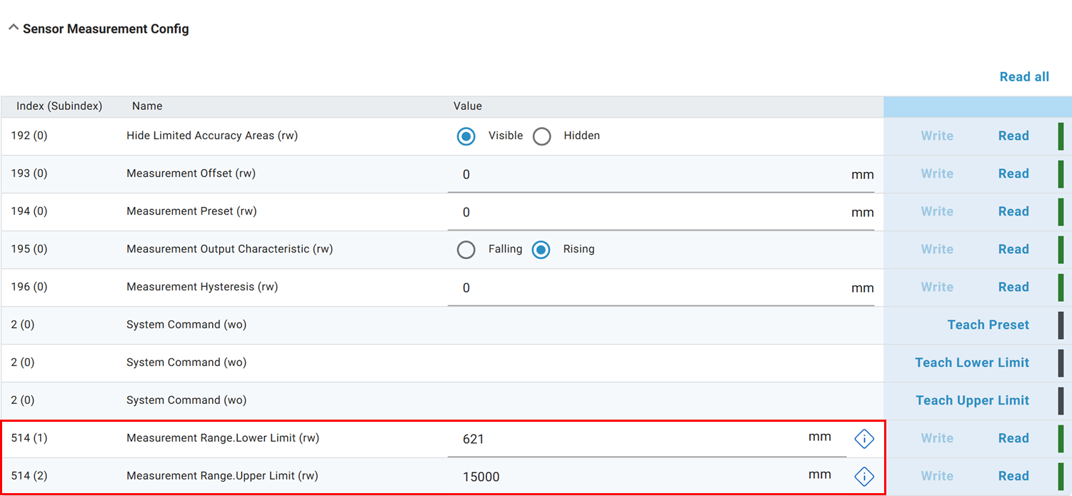
Distance: Scaled based on the configured measurement range (see step 4). Factory setting: 300 mm to 15000 mm → for 4-20 mA this means 4 mA = 300 mm and 20 mA = 15000 mm.
Magnitude: Fixed range 0 dB to 64 dB → for 4-20 mA this means 4 mA = 0 dB and 20 mA = 64 dB.
3. Configure type
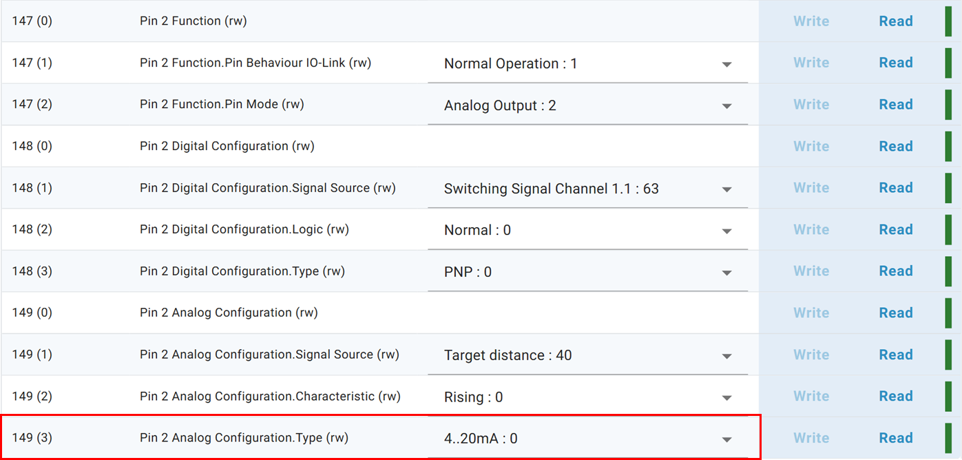
The analog output supports the following current and voltage signals:
4-20 mA
0-20 mA
1-5 V
0-10 V
2-10 V
Note
Current and voltage ranges are nominal. Error and status conditions can exceed upper or lower limits.
Value |
Meaning |
|---|---|
11 V / 22 mA |
Sensor in error state |
10.5 V / 20.5 mA |
Measured value above measurement range |
−0.5 V / −0.5 mA |
Measured value below measurement range |
4. Configure measurement range
The measurement range defines scaling (lower / upper limit) for distance. Configuration under Sensor Measurement Config.
Warning
The measurement range also defines the safe measurement range. Values outside the safe range are indicated by a yellow blinking LED.
Convert analog values
Conversion
Calculation of output current or back‑calculation to distance:
\(I_{\text{out}}\): output current
\(I_{\text{min}}\): lower current limit (e.g. 4 mA)
\(I_{\text{max}}\): upper current limit (e.g. 20 mA)
\(x\): measurement value (distance mm or magnitude dB)
\(x_{\text{min}}\): lower measurement range limit
\(x_{\text{max}}\): upper measurement range limit
Tip
For distance the measurement range is configurable. Factory settings: 300 mm to 15000 mm. For magnitude the range is fixed at 0 dB to 64 dB.
Example: For a measurement of 800 mm in the range 300–1300 mm:
Analog voltage:
\(U_{\text{out}}\): output voltage
\(U_{\text{min}}\): lower voltage limit (depends on type)
\(U_{\text{max}}\): upper voltage limit
\(x\): measurement value (distance mm or magnitude dB)
\(x_{\text{min}}\): lower measurement range limit
\(x_{\text{max}}\): upper measurement range limit
Step 4 – Object detection