Connection & Commissioning
Chapter goal
Goal: Make the sensor visible in your Master and obtain first measurement values.
Prerequisite
The CMTK must be set up according to its own manual (Network, access, basic function). These steps are not part of this guide. For IO-Link Masters this guide uses the Balluff Engineering Tool. If you are using this also first read its manual and the manual of your IO-Link Master before using this guide.
1. Mount and connect the sensor
Mount the sensor rigidly and aligned exactly towards the target to be measured. Even slight angle changes (e.g. holding the sensor in your hand) lead to fluctuating values.
Connect the sensor with the IO-Link Master, power on the IO-Link Master and connect it to your PC. Make sure your PC and the IO-Link Master are in the same Network. Open the Balluff Engineering Tool and go to “Scan”
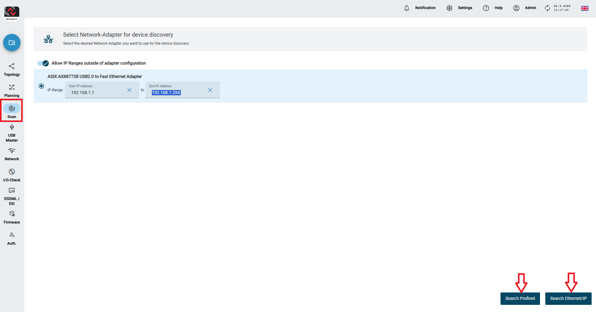
Select the Network Adapter which connects the IO-Link Master and your PC. After that press either Scan Profinet or Scan Ethernet/IP depending on your IO-Link Master. If everything worked, it should look like that:
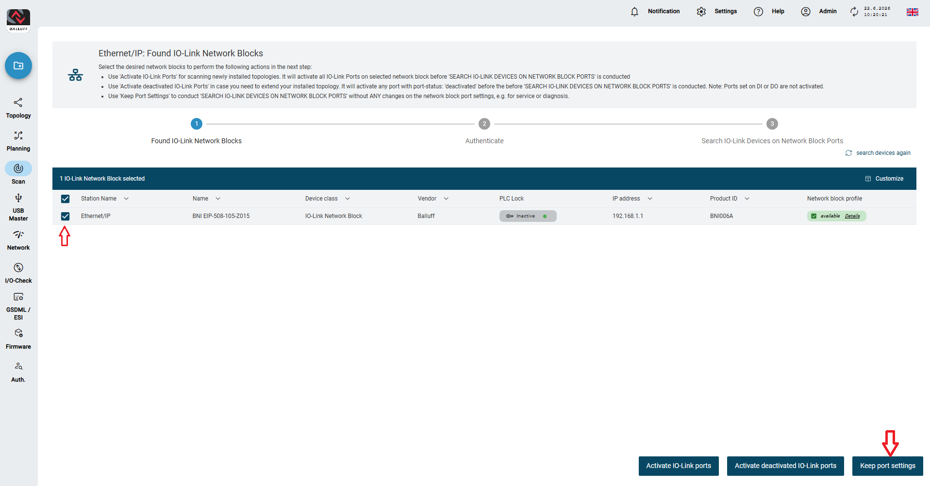
Your Name, IP Address and Product ID may differ if you use a different IO-Link Master.
Select your IO-Link Master. After that go to Keep Port settings. After some seconds your IO-Link Master should be added to your Balluff Engineering Tool.
Connect the sensor via a suitable M12-to-M8 cable to an IO-Link Port of the CMTK. If the CMTK is powered, at least one green LED should light or blink (Sensor ready / IO-Link connection). The second LED can be off or yellow – both are fine.
2. Upload IODD
Normally the Balluff Engineering Tool should recognize all Balluff Products and assign the right IODD. If that doesn’t work, you can upload the IODD by manually, like shown in the image:
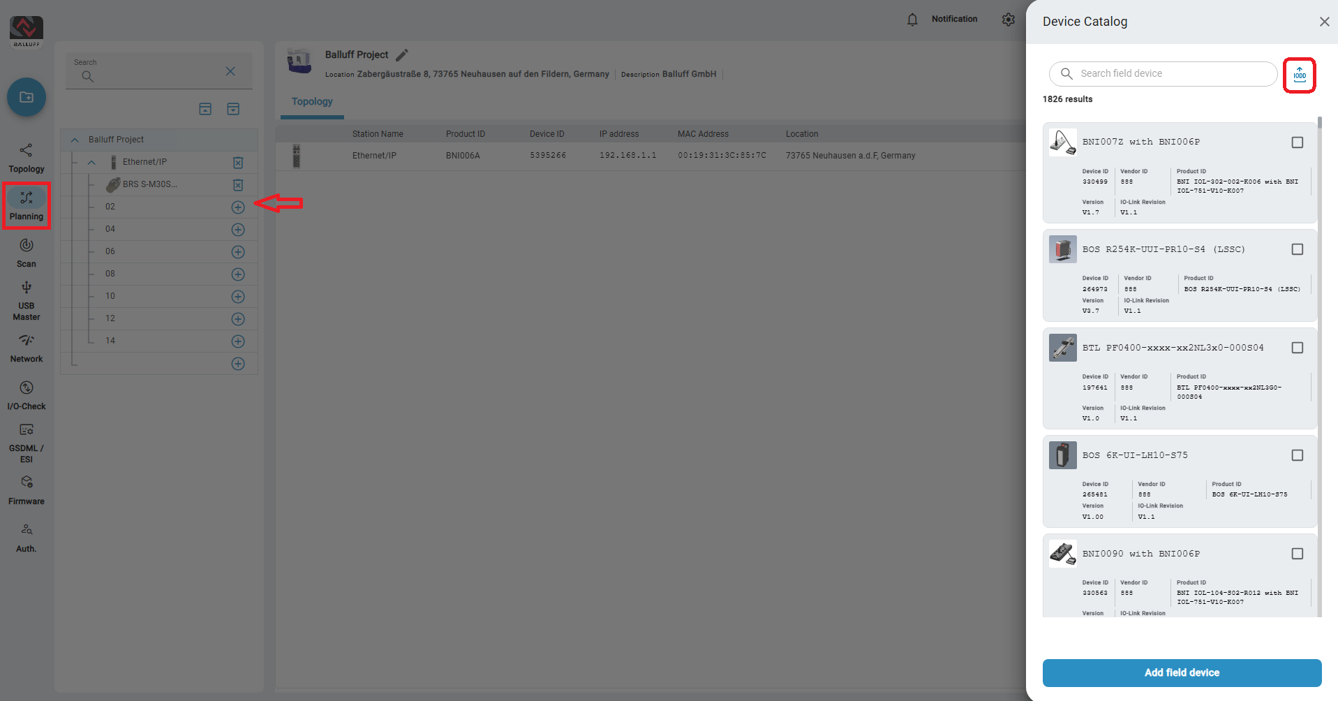
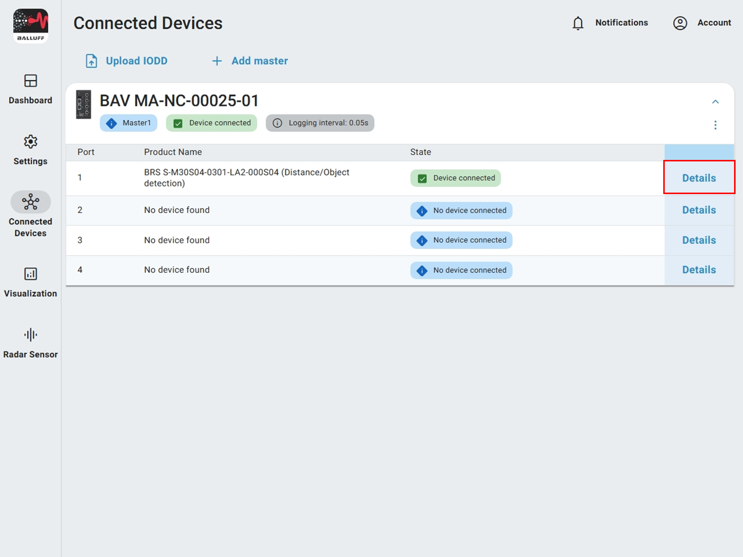
First go to Scan and open the connections from your IO-Link Master. Select the Port your sensor is connected to. After that click on the IODD Icon and select your IODD.
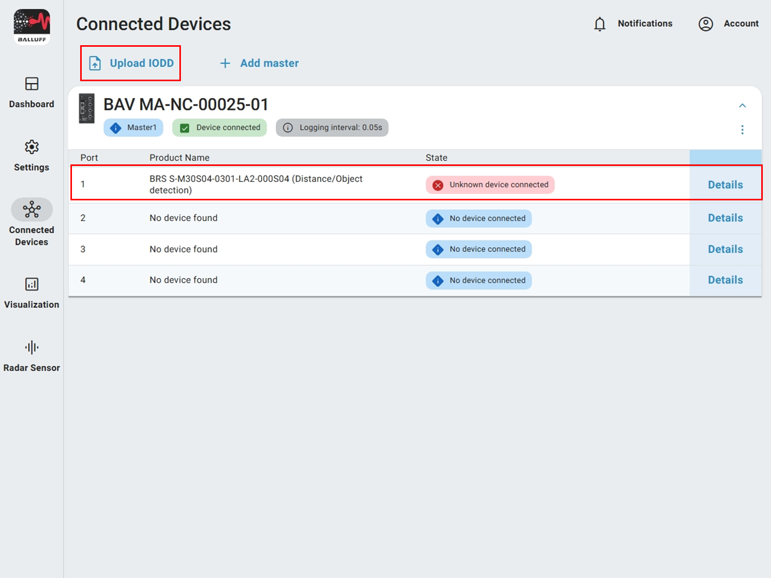
If the sensor appears with status Unknown device connected, the CMTK does not yet know the IODD. Download the correct IODD from the Balluff Update Platform. For the standard mode you need the variant BRS S-M30 (Distance/Object detection). Import it via the Upload IODD button.
Tip
Unzip the ZIP file before uploading.
3. Reset sensor to factory settings
Set the sensor to factory settings to obtain a defined starting point.
Warning
All sensor settings are reset and lost irreversibly.
To reset your sensor you need to click on your sensor, go to Parameters, search for General Settings and click on Device Reset.
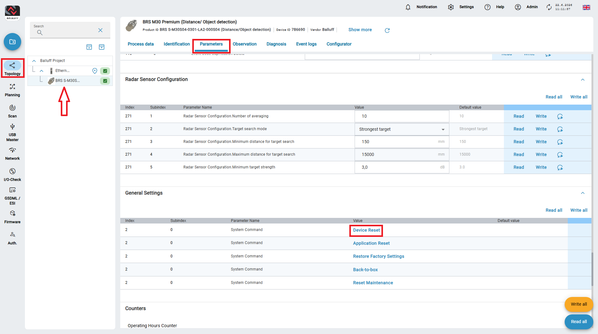
You can find parameters in the CMTK under Parameters (IODD) → Parameters. Select the sensor under Connected devices first.
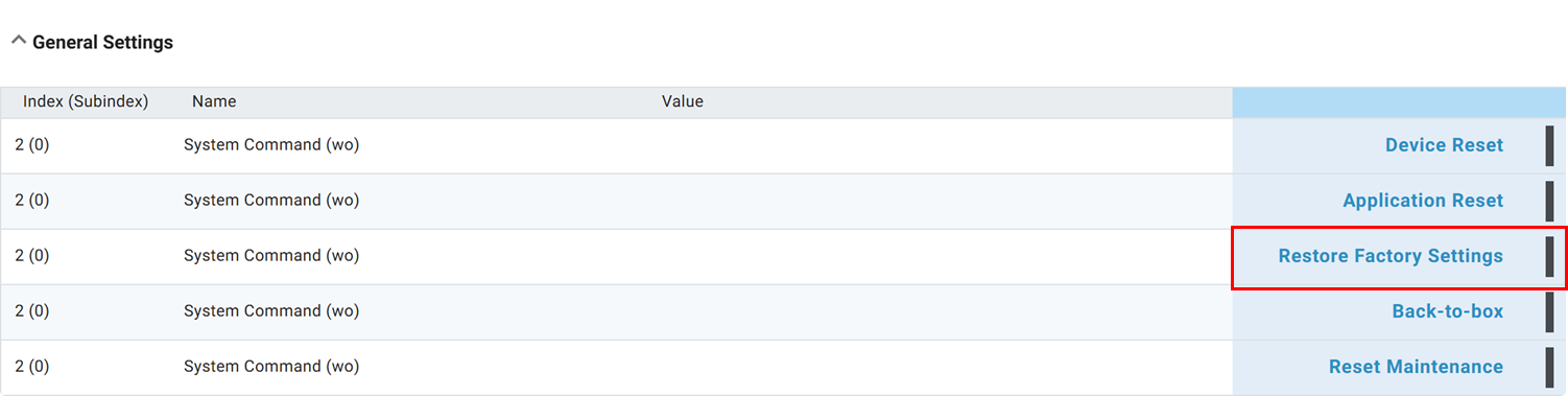
Go to General Settings → Restore Factory Settings.
4. Interpret process data
The current process data of the sensor is shown in the process data view under Process data after you click on your sensor. For a start, the values MDC1 (Target distance) and MDC2 (Target strength) are especially relevant.
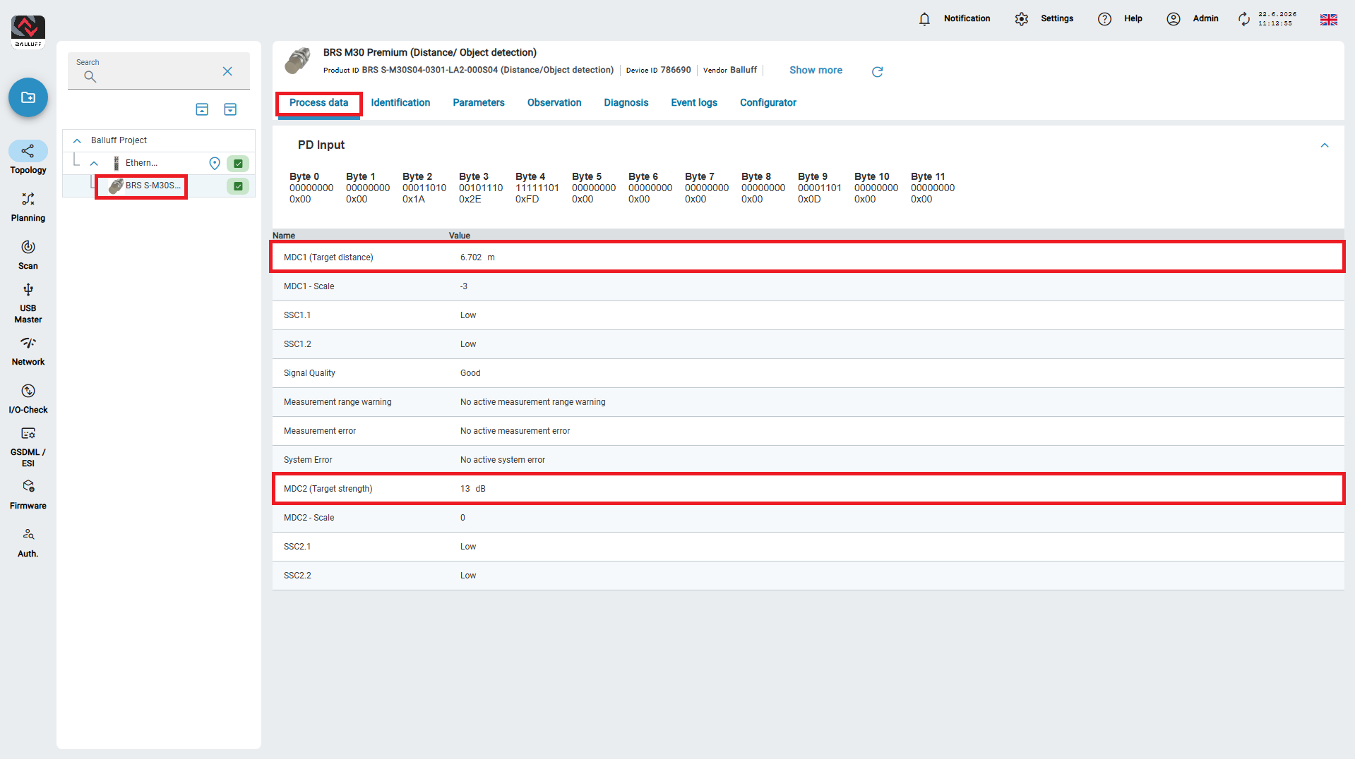
The current process data of the sensor is shown in the process data view under Details.
For a start, the values MDC1 (Target distance) and MDC2 (Target strength) are especially relevant.

MDC1 (Target distance) – Distance
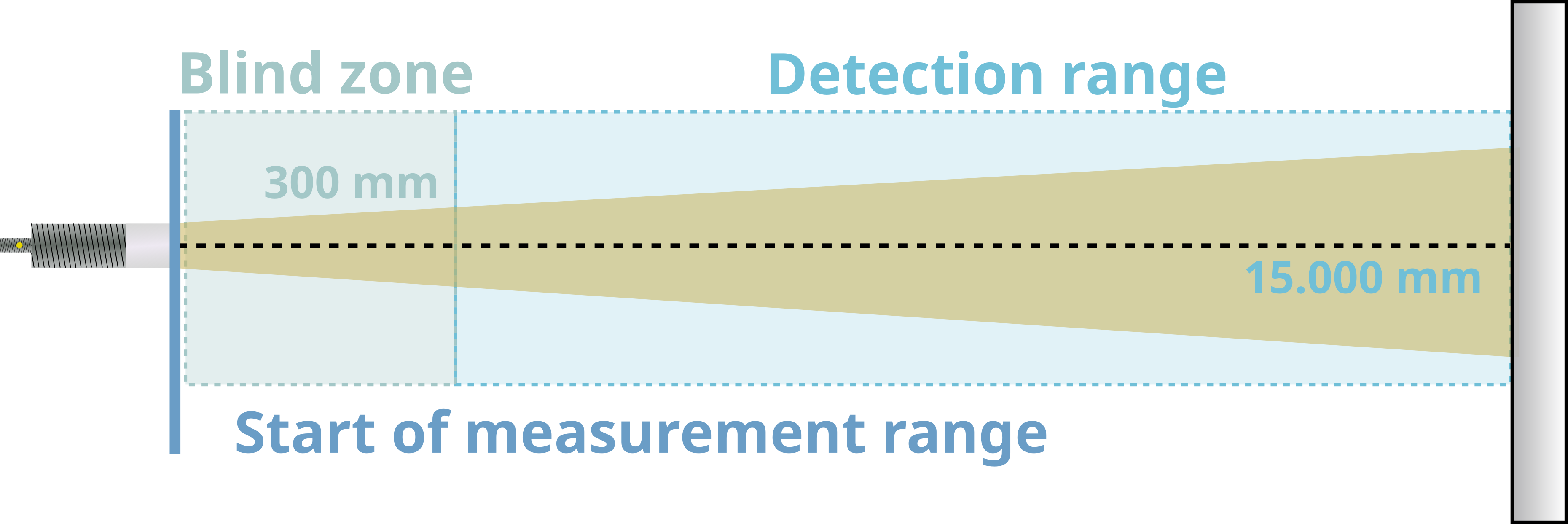
Distance is the measured range (in meters) to the currently selected target. The usable measurement range extends up to 15 m. Below approx. 300 mm the blind zone begins; accuracy drops significantly there. By default the sensor reports objects from about 150 mm however, measurement error can exceed ±10 mm there. For reliable results the target should be outside the blind zone.
Detection range and blind zone
My distance value is wrong
Tips for optimization are in the next chapter.
MDC2 (Target strength) – Magnitude
Magnitude describes reflection strength at the computed distance. Different materials and surfaces (metal, plastic, angle, curvature) reflect differently. Matte or angled surfaces often yield lower values. The mounting angle has a strong influence. Therefore a clean mounting and alignment are crucial. Align the sensor so magnitude is as high as possible.
Reflectivity of materials
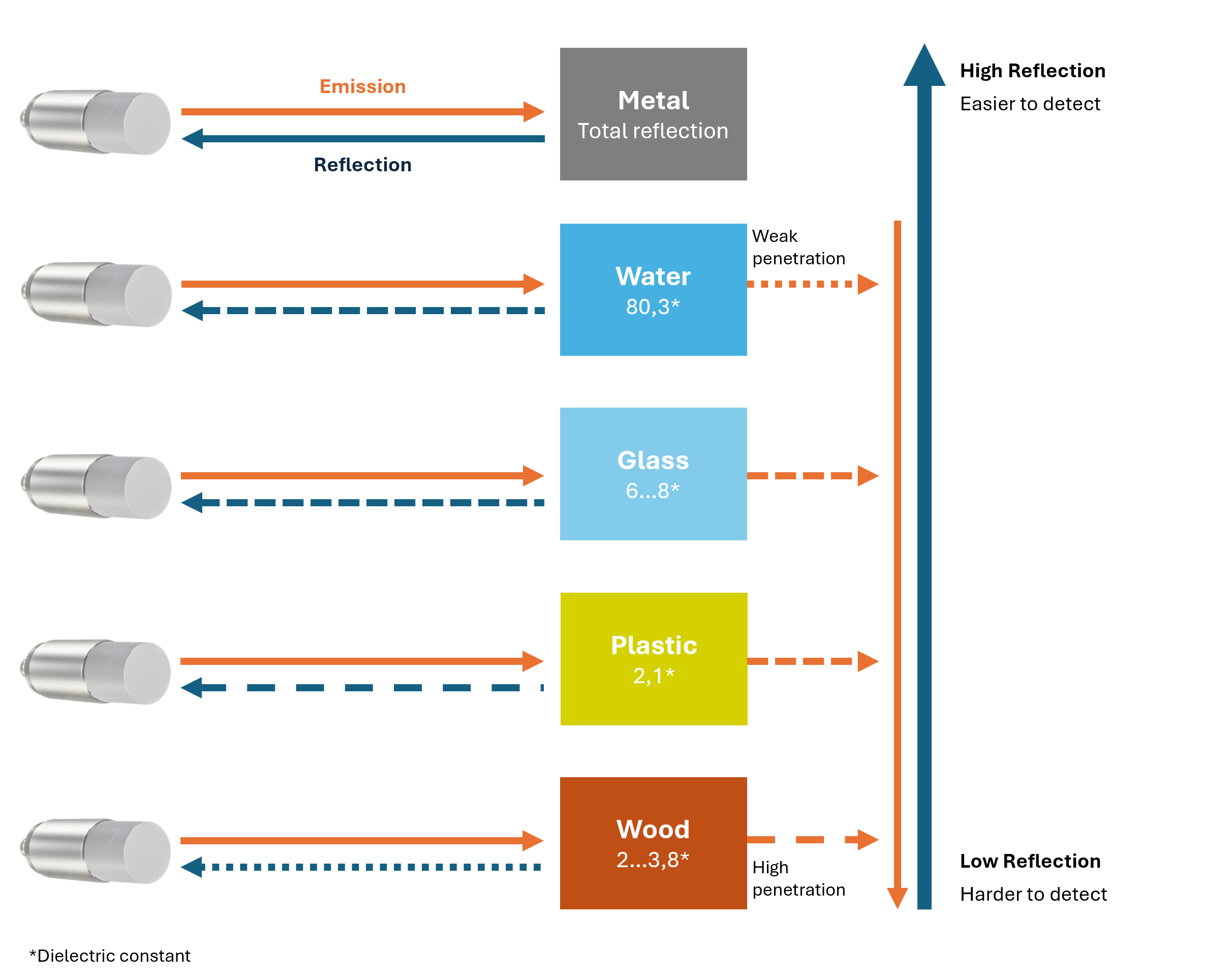
More information on reflectivity is in the Excursus – How does a radar sensor work and the Manual.
5. Visualize process data
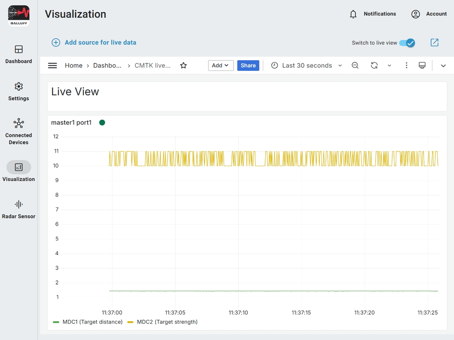
With the CMTK you can visualize the course of process data – recorded values and live data. This helps especially during alignment.
Tip
This only works on the CMTK. Details on visualization are in the CMTK Manual.
Step 2 – Distance measurement – Understand & Optimize