Digital Output
Chapter goal
Goal: Output a detected object via a digital output.
Prerequisite
The configuration and monitoring tool (CMTK) is used here only for parameterization. It displays the state of pins 2 and 4 but cannot record or further process them.
How it works
The sensor can output two switching channels via digital outputs. These share pins with analog output and IO-Link – you must decide on usage.
Parameters are summarized in the following table.
Use of IO-Link pin
The IO-Link pin automatically detects an IO-Link master, activates IO-Link and disables the digital output. This behavior cannot be overridden.
Parameter table
Pin assignment

PIN |
Function |
|---|---|
1 |
24 V |
2 |
Digital output / Analog output |
3 |
0 V |
4 |
IO-Link / Digital output |
Configuration
1. Configure object detection
First set up object detection – alternatively you can output certain system states.
Possible output signals
2. Configure pin mode and signal source
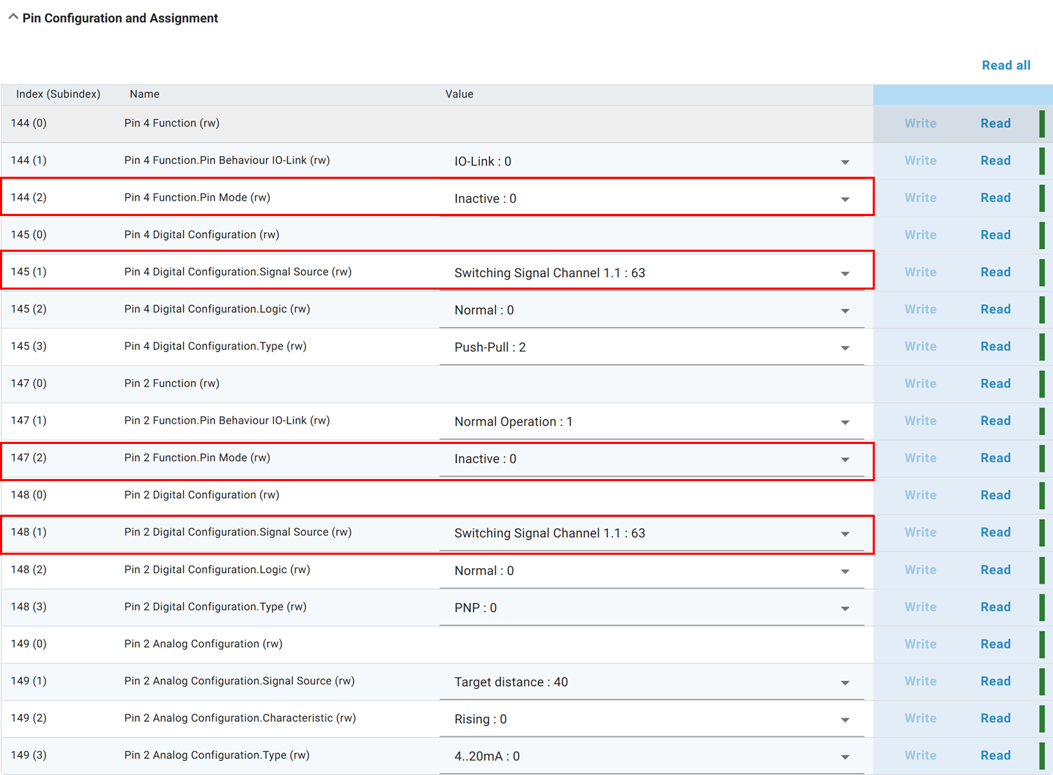
Set pin mode to Digital Output and choose the desired switching channel as signal source. The pin configuration settings are under Pin Configuration and Assignment.
3. Configure switching type
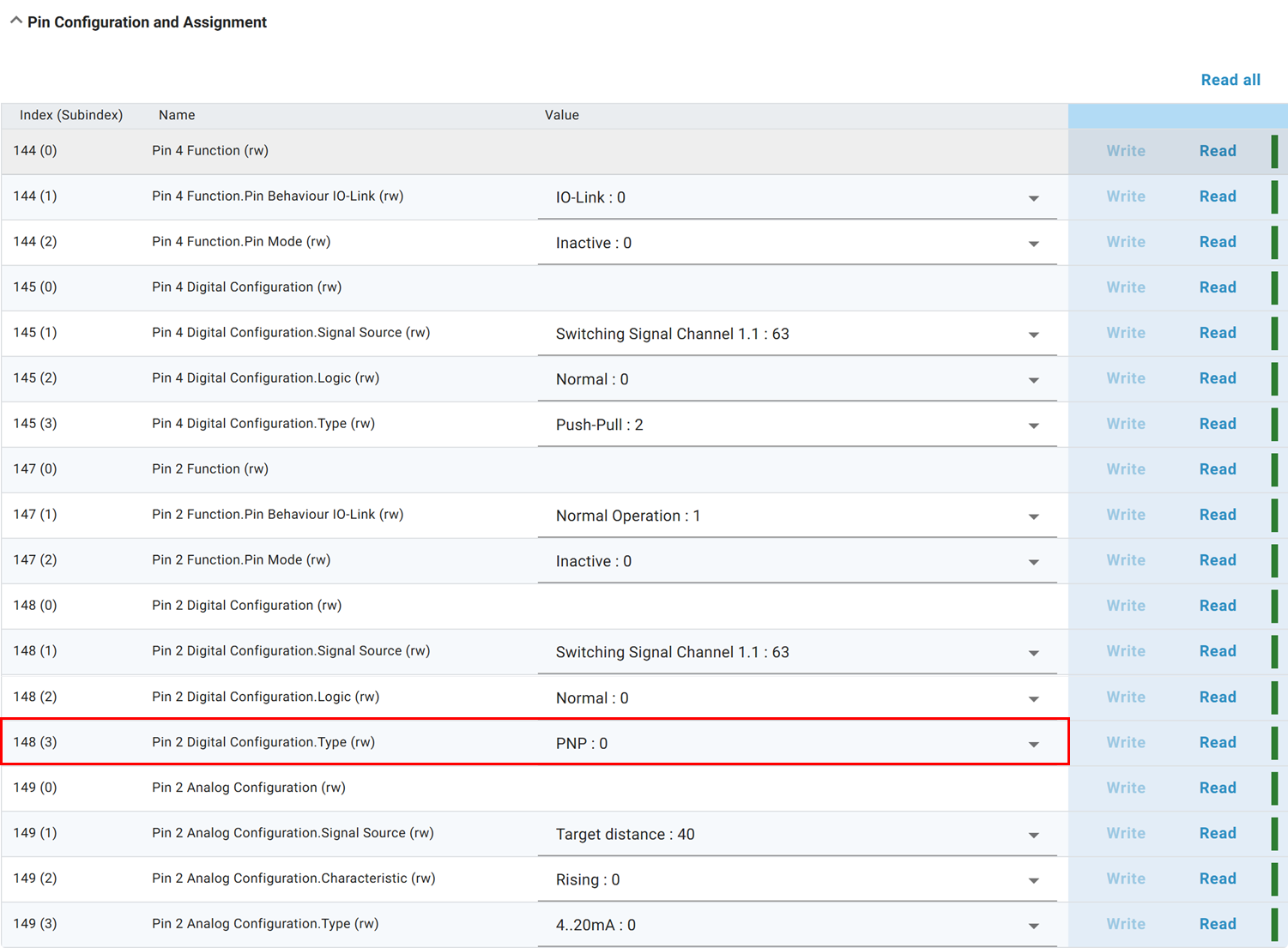
Pin 4 supports only Push-Pull. Pin 2 supports PNP, NPN or Push-Pull.
Note on Pin 4
Pin 4 is used for IO-Link communication by default. If the sensor is connected to an IO-Link master or similar devices, the device automatically detects the connection, activates IO-Link communication, and disables the digital output functionality on Pin 4.
This behavior cannot be overridden.
As a result, Pin 4 cannot be used as a digital output while an active IO-Link connection is present. The pin is exclusively reserved for communication in this case.
For testing or using the digital output function of Pin 4, the IO-Link connection must be inactive or not established. Alternatively, use Pin 2, which can be configured as a digital output independently of IO-Link communication.
Switching types
PNP: The output supplies +24 V when active. The load or PLC input is connected between the output and 0 V.
NPN: The output switches to 0 V when active. The load or PLC input is connected between +24 V and the output.
Push-Pull: The output actively drives the signal both high (+24 V) and low (0 V). It can therefore be used with many PNP- or NPN-compatible inputs, depending on the wiring and input specification.
Step 6 – Radar Reflex Gate mode – Near-range object detection