Quick Start - Introduction
Welcome to the quick start for the Balluff Radar Sensor BRS0002.
This quick start walks you step by step through commissioning the sensor with the Balluff Condition Monitoring Toolkit (CMTK) or a Balluff IO-Link Master. It shows you how to adjust the most important parameters. The focus is deliberately on the practical workflow – in‑depth background information is provided in the manual.
Safety
Before mounting, wiring and configuring, read the Safety notes.
This quick start does not replace the manual, it remains authoritative. You will find further information there.
Excursus – How does a radar sensor work?
Radar sensors determine distance by emitting electromagnetic waves and evaluating their echoes. The BRS0002 uses FMCW (Frequency Modulated Continuous Wave).
In FMCW operation the sensor continuously changes its transmit frequency in rising and falling ramps (“chirps”). When the signal hits an object, the echo returns time‑shifted. All reflected echoes form a spectrum. The peaks in this spectrum can be converted into a distance.
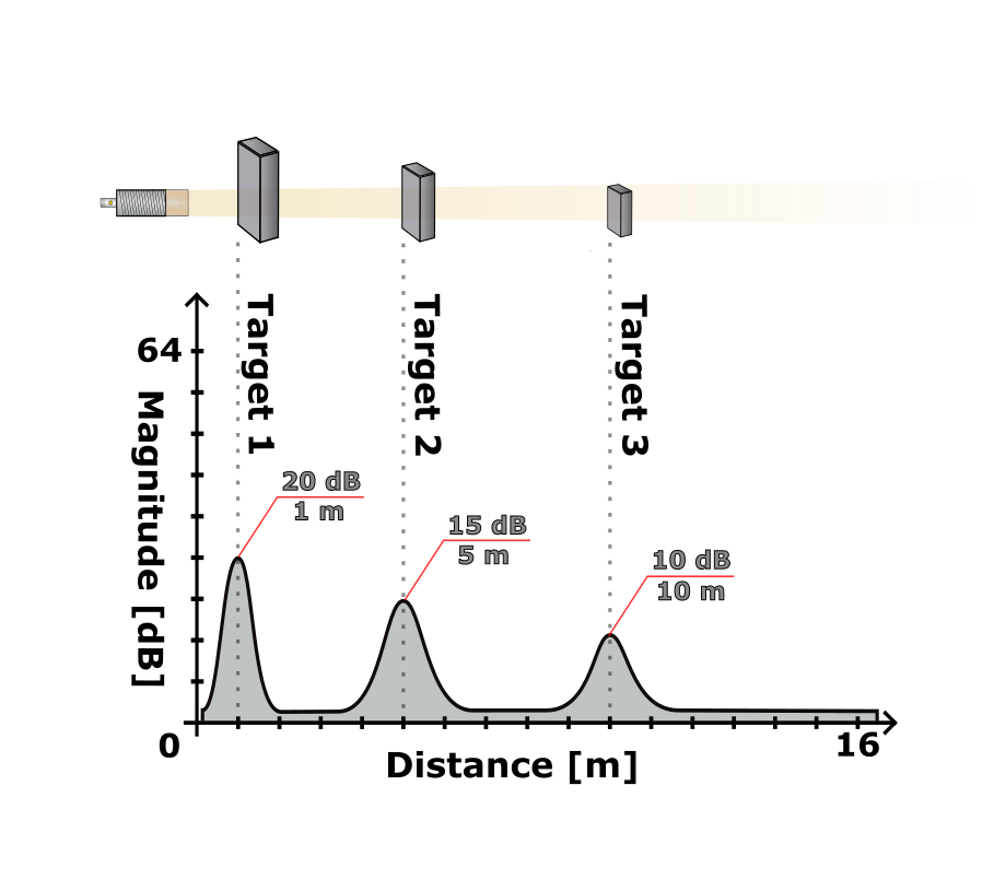
The magnitude of a peak describes the strength of the received echo. It is influenced by material properties (conductive / dielectric), size and orientation of the surface, surface texture (smooth vs. rough), distance (two‑way attenuation), angle as well as shadowing or multi‑path. Magnitude is relative – comparisons under identical conditions are more meaningful than individual values.
Materials: Metals reflect strongly. Dry non‑conductive materials (e.g. some plastics, wood) allow part of the energy to pass; objects behind can be visible provided their echo is not masked. Moist or water‑containing substances attenuate more strongly and reduce visibility of targets behind. “Penetration” means: An attenuated portion passes through – not fully “see‑through”. More information on reflection properties is in the Manual.
Geometry: Frontally aligned, flat surfaces deliver strong peaks. Angled or strongly curved surfaces deflect energy away – the echo is weaker. Round or cylindrical shapes scatter; edges or corners can locally amplify. Each peak is the interplay of material, shape, angle and distance. Changes over time or differences between defined states provide the greatest information gain.
Prerequisites
Hardware: Balluff Radar Sensor BRS0002
Cable: Suitable M12 connection cable (4‑pin for analog and digital output)
IO-Link Master: This quick start uses an IO-Link Master and the CMTK. You can choose which one you want to use. Other IO-Link masters can also be used.
Factory settings and order
This quick start assumes the sensor is at factory settings and the sections are performed in the order shown. To set the sensor to factory settings at the beginning, follow the steps in the commissioning chapter.
Note on analog/digital output
The quick start demonstrates output configuration. The CMTK itself is only used for parameterization – for actual measurement or verification of a current/voltage value (analog) or switching level (digital) you must connect the sensor afterwards to appropriate evaluation or control technology (e.g. PLC, measuring device).
Using another IO-Link master
You can operate the sensor with any other IO-Link master. Configure parameters directly via ISDU indices or load the IODD. Relevant indices are listed in each section’s parameter tables. Read your master’s manual for the specific steps.
Glossary
Glossary
Step 1 – Connection & Commissioning