Distance Measurement – Understand & Optimize#
Chapter goal
Goal: Understand how distance measurement works and learn which parameters optimize it.
Prerequisite
For this chapter the Radar Sensor Blob UI app on the CMTK is helpful. It is available in the App Store (installation info in the manual).
The Radar Sensor Blob UI also exists as a plugin for the Balluff Engineering Tool (BET). Plugins are shipped with the BET. Using BET you can connect Balluff IO-Link masters via Ethernet or USB.
Optimization is possible without visualization – you will simply miss raw data insights.
How it works#
Factory settings make the sensor determine the distance of the strongest target. Relevant parameters are listed below; their effect is described afterwards.
Parameter table
ParameterSectionParameter name |
IndexSubindex |
Default |
|---|---|---|
Lower limit measurement rangeSensor Measurement ConfigMeasurement Range.Lower |
5141 |
300 mm |
Upper limit measurement rangeSensor Measurement ConfigMeasurement Range.Upper |
5142 |
15000 mm |
Target search modeRadar Sensor ConfigurationTarget search mode |
2712 |
Strongest target |
Minimum target search distanceRadar Sensor ConfigurationMinimum distance for target search |
2713 |
150 mm |
Maximum target search distanceRadar Sensor ConfigurationMaximum distance for target search |
2714 |
15000 mm |
Minimum target strengthRadar Sensor ConfigurationMinimum target strength |
2715 |
3 dB |
Averaging countRadar Sensor ConfigurationNumber of averaging |
2711 |
10 |
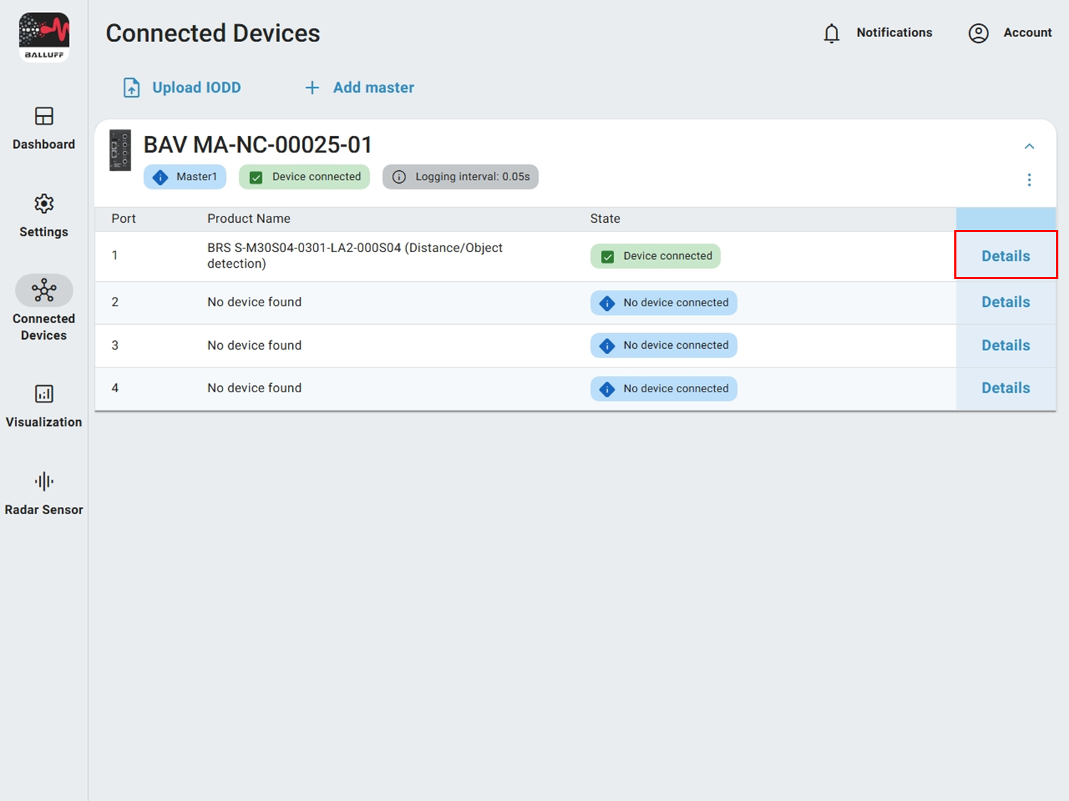
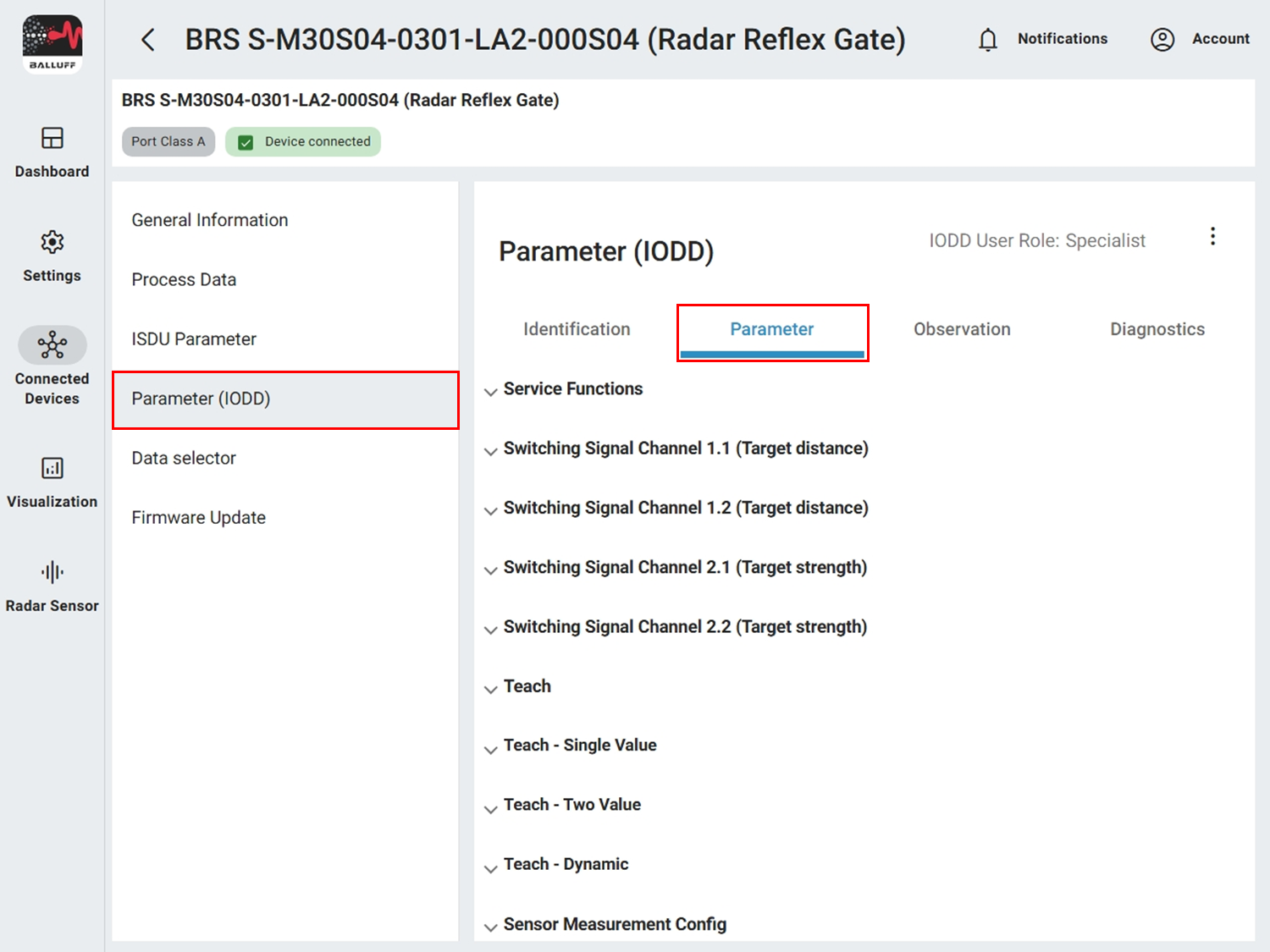
Find the parameters in the CMTK under Parameters (IODD) → Parameters after selecting the sensor under Connected devices.
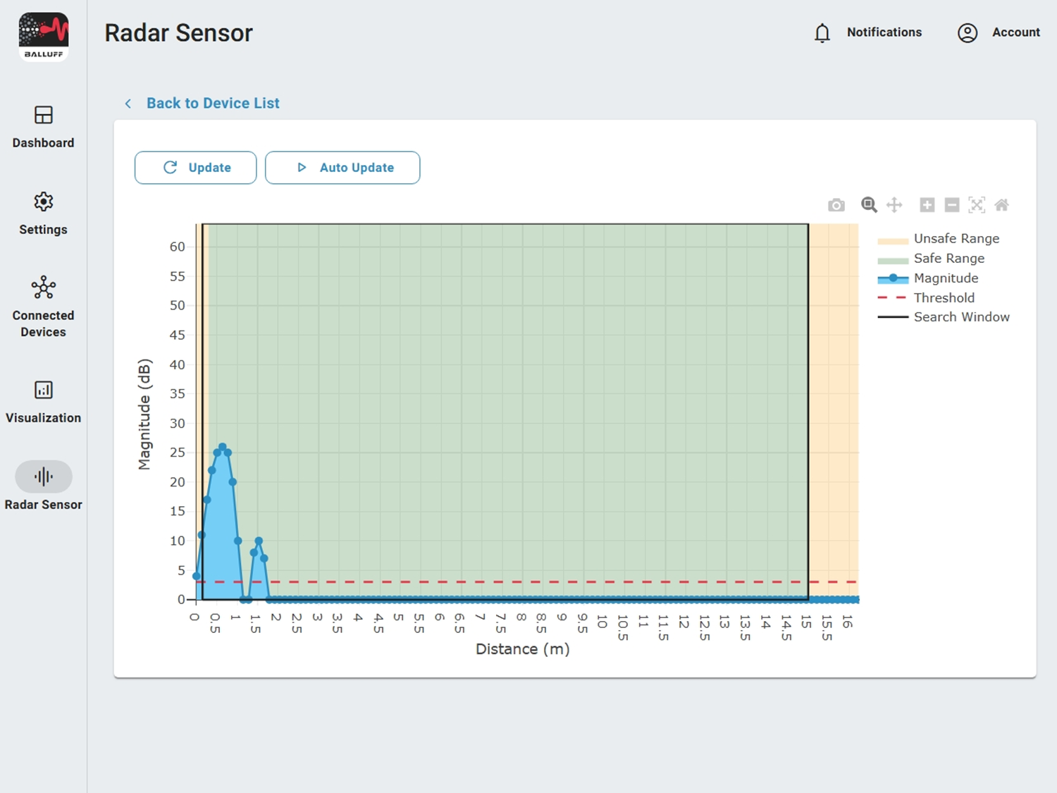
You can ideally visualize their relationship with the Radar Sensor Blob UI. Open it under Radar sensor, refresh once with Update or enable Auto Update.
Magnitude#
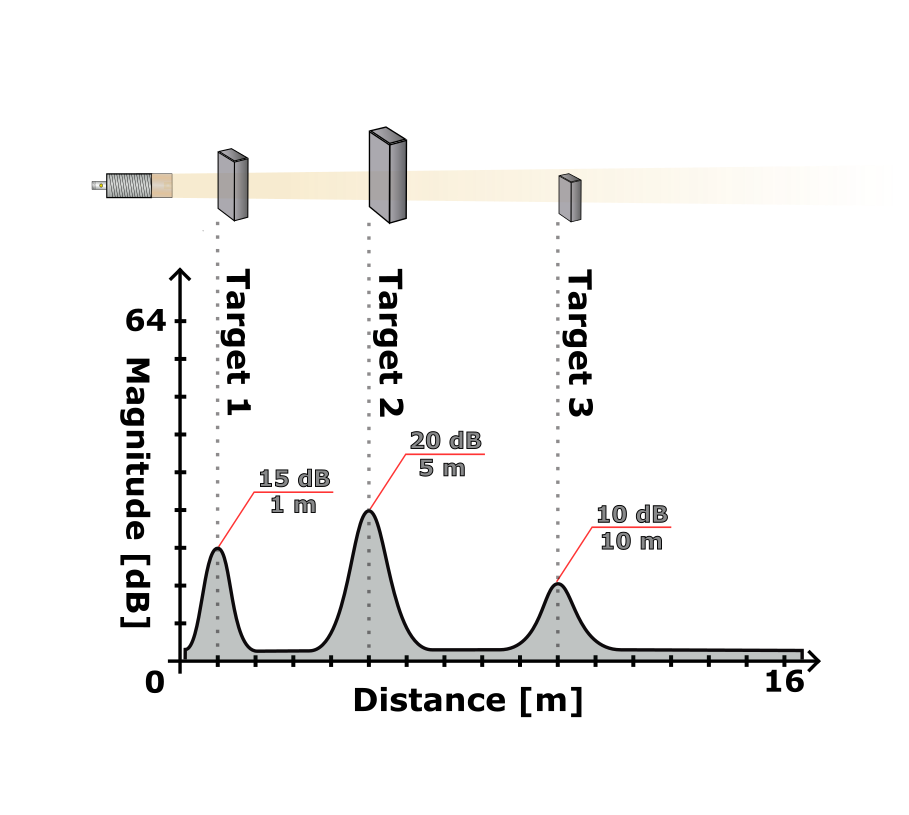
Magnitude (blue line) shows the reflection strength of an object at a certain distance. The higher the value, the stronger the reflection. See also Commissioning.
Target search mode, search window and minimum target strength#
In the standard mode Strongest target the sensor selects the highest magnitude peak within the search window (min/max target search distance; black rectangle). A target must also lie above the threshold (dashed red line = minimum target strength).
Important
The strongest value must be a pronounced peak (peak = central value with both neighbors smaller). The visualization shows rastered values. The computed value can lie slightly outside the search window although the peak visually still appears inside – in this case it is discarded.
Measurement range#
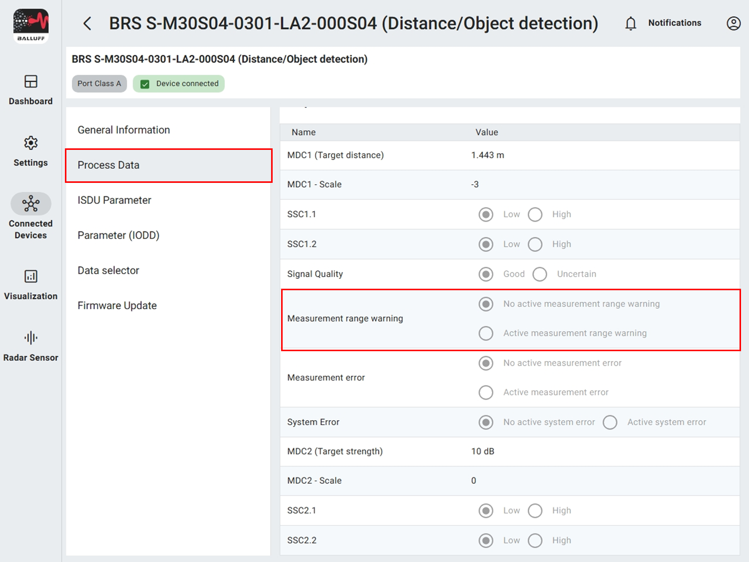
The measurement range splits into safe and unsafe portion. In the near range the sensor can detect objects but accuracy drops significantly (> ±10 mm). The effective limit depends on application, environment and target reflection. Unsafe values are signaled via LEDs (yellow blinking) and via process data.
Configuration#
Optimize distance measurement#
If multiple objects cause the wrong target to be chosen or values fluctuate strongly, you can adjust settings. The settings are under Radar Sensor Configuration. Typical workflow comprises four steps:
1. Configure search window#
Set min and max target search distance so irrelevant targets are excluded (values in mm).

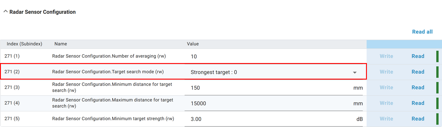
2. Configure target search mode#
If the search window is insufficient, switch from Strongest target to Nearest target (first object above threshold).
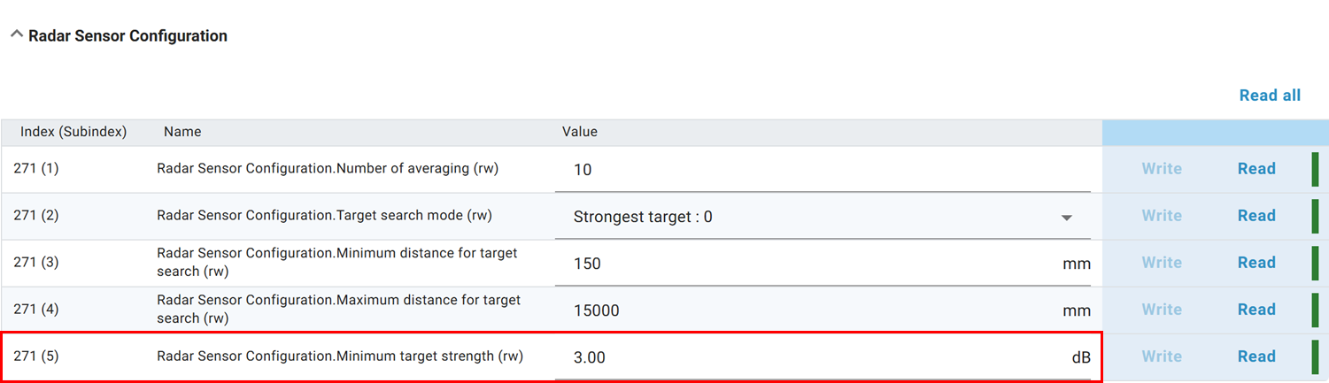
3. Configure minimum target strength#
Increase or decrease minimum target strength to ignore weak targets or allow additional ones.
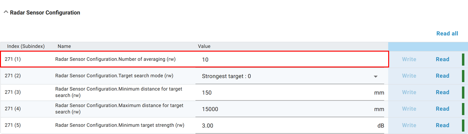
4. Configure averaging#
Adjust averaging (moving average of last n measurements) – more smoothing vs. reaction speed.
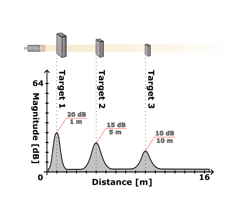
Examples#
Configuration scenarios
In each example minimal configuration changes show how the respective object can be detected. Deviations from the defaults are highlighted in bold.
| Object | Search window | Target search mode | Minimum target strength |
|---|---|---|---|
| 1 | 300–15000 mm | Nearest target | 3 dB |
| 2 | 300–15000 mm | Strongest target | 3 dB |
| 3 | 6000–15000 mm | Strongest target | 3 dB |
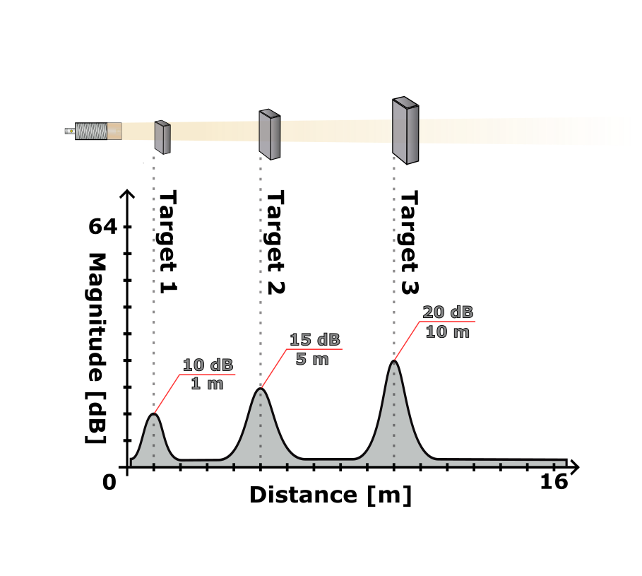
| Object | Search window | Target search mode | Minimum target strength |
|---|---|---|---|
| 1 | 300–15000 mm | Strongest target | 3 dB |
| 2 | 2000–15000 mm | Strongest target | 3 dB |
| 3 | 6000–15000 mm | Strongest target | 3 dB |
| Object | Search window | Target search mode | Minimum target strength |
|---|---|---|---|
| 1 | 300–15000 mm | Nearest target | 3 dB |
| 2 | 300–15000 mm | Nearest target | 12 dB |
| 3 | 300–15000 mm | Strongest target | 3 dB |
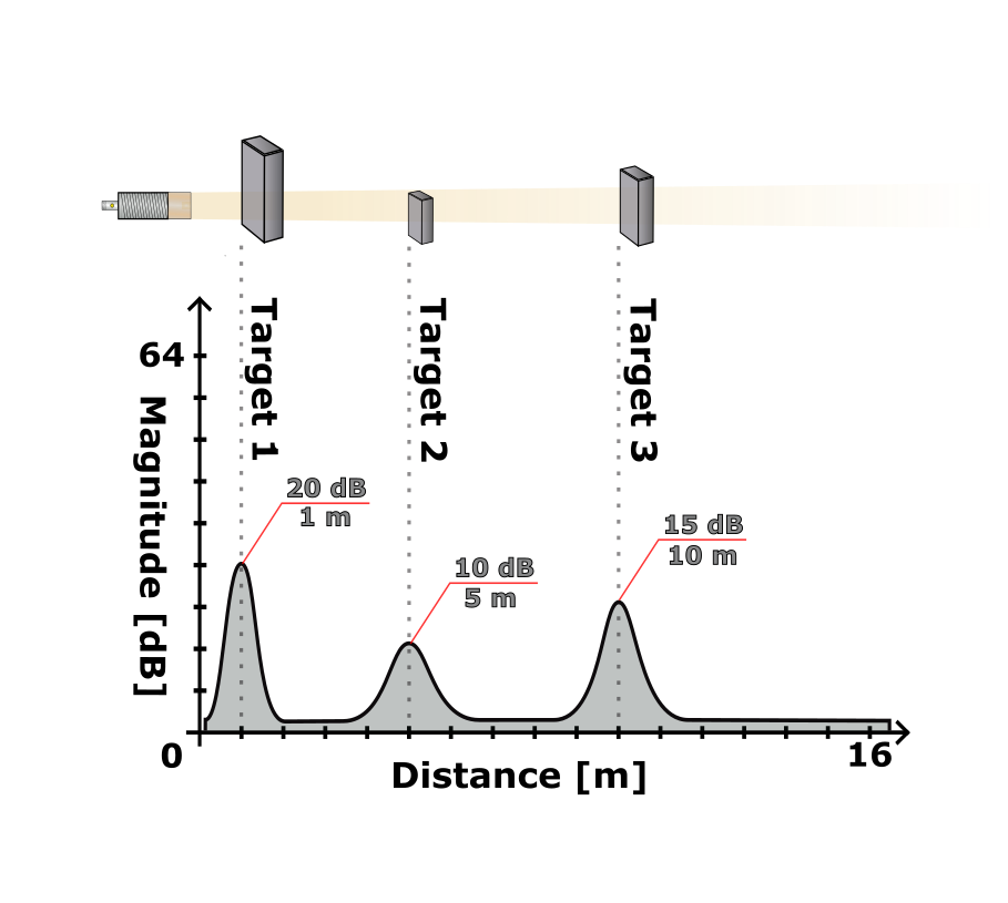
| Object | Search window | Target search mode | Minimum target strength |
|---|---|---|---|
| 1 | 300–15000 mm | Strongest target | 3 dB |
| 2 | 2000–15000 mm | Nearest target | 3 dB |
| 3 | 2000–15000 mm | Strongest target | 12 dB |
Configure measurement offset#
If you mount the sensor further away (to bypass near‑range inaccuracy) you can set a measurement offset.
Parameter table
ParameterSectionParameter name |
IndexSubindex |
Default |
|---|---|---|
Measurement offsetSensor Measurement ConfigOffset Distance |
1930 |
0 mm |
Preset distanceSensor Measurement ConfigPreset Distance |
1940 |
0 mm |
Teach Preset (Command)Sensor Measurement ConfigStandard Command |
20 |
Teach Preset |
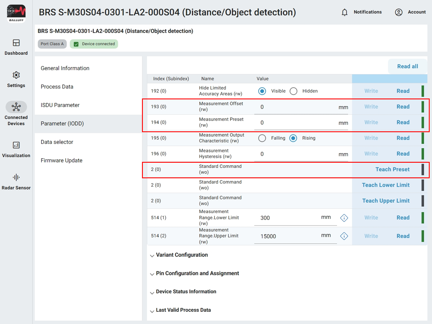
You can enter the offset manually (value is subtracted from measurement) or calculate it automatically.
Examples
Example 1: Measured value is currently 1.5 m but should be 1 m. Difference 500 mm. Enter 500 mm into Measurement offset.
Example 2: Measured value is currently 1.5 m but should be 2 m. Difference −500 mm. Enter −500 mm into Measurement offset.
For automatic configuration place the object at a defined position (e.g. 2 m), enter that value (2000 mm) into Preset distance and execute Teach Preset. The offset is set so the measured value afterwards is 2000 mm.
- Next section
Step 3 – Analog output