Frequently Asked Questions (FAQ)
Jun 12, 2025 | 2722 words | 14 min reading time
Compatibility FAQ
Which IO-Link network modules are compatible with the BET ?
The following IO-Link network modules are supported:
IO-Link network modules for Profinet bus networks (BNI PNT series with firmware > 3.2.2 or higher) with IO-Link ports.
IO-Link network modules for Ethernet-IP bus networks (BN EIP series with firmware from 4.0 or higher) with IO-Link ports.
The IO-Link network modules BNI00HL (FW version 1.0) and BNI00HM (FW version 1.1) are only partially supported.
IO-Link network modules from other manufacturers: The BET implements the JSON for IO-Link specification (as of March 2020). IO-Link network modules from other manufacturers that comply with this specification are generally compatible. However, there may be functional restrictions.
Not supported:
Purely digital IO-Link network modules for Profinet and Ethernet IP bus networks without IO-Link ports
IO-Link network modules for EtherCAT
Which IO-Link devices are compatible with the BET ?
All IO-Link devices from IO-Link version 1.1 can be set and configured with the BET . The display of the parameters and process data corresponds to the status of IO-Link specification 1.1.2
FAQs about firewall and IO-Link network
Setting the firewall for the scanning process
The BET uses UDP and ICMP communication as well as HTTP REST over TCP and the DCP, CIP and ARP protocols to identify IO-Link network modules.
The UDP protocol works according to the “fire and forget” principle: A request is sent to all IO-Link network nodes (broadcast) with no guarantee that a “response” will be returned. This procedure can lead to the firewall blocking the task and interrupting the scan process in BET .
You must therefore add the BET to the Windows Firewall as an exception for the following incoming and outgoing connections. For the error-free operation of the BET , outgoing and incoming traffic to private and public networks must be allowed.
UDP protocol: UDP uses ports 2000 (incoming) and 1999 (outgoing).
CIP protocol: CIP uses port 44818 (outgoing) as well as 2222 (incoming).
If another firewall is used or adding new firewall entries is blocked, the system administrator should be consulted. The firewall must be enabled accordingly.
To find IO-Link network modules with the BET , the network adapter used to search for devices must be in the same IP address range as the devices to be operated (IO-Link network module and IO-Link devices).
How should the firewall be configured to perform the scan successfully?
During the first scan process after installing BET , the firewall blocks the scan process:
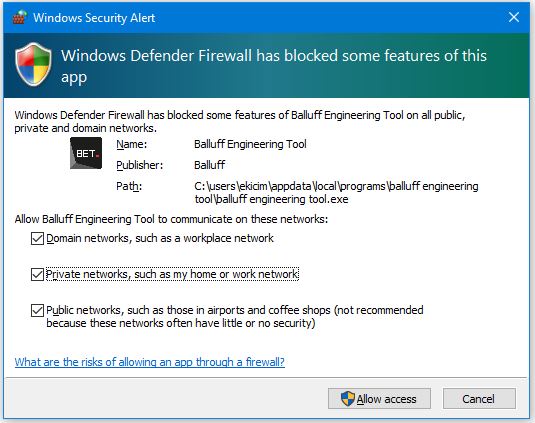
Enable all networks to allow access for communication setup.
To verify that these rules are deployed in the firewall, follow these steps:
Click the Windows Start menu, search for Check Firewall Status, and click Open.
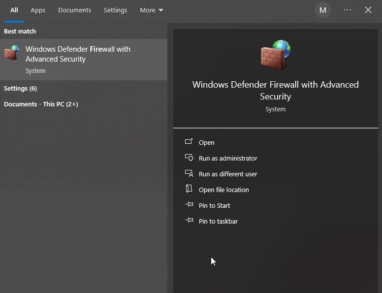
The following dialog appears:
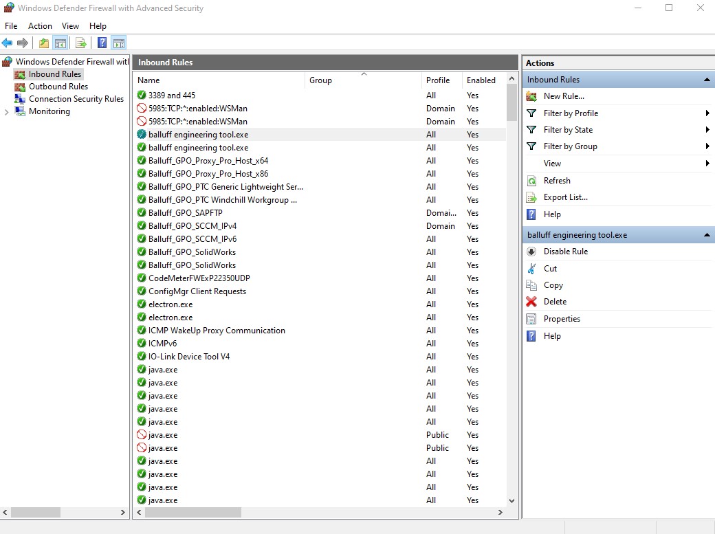
Click Incoming rules, and under Incoming rules click the entry balluff engineering tool.exe. Then navigate to the Advanced tab.
The following dialog appears:
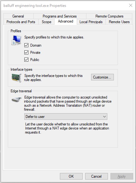
Activate all three profiles under Profiles:
*domain
*Private
*Public
Click OK.
The firewall is configured to perform the scanning process.
Second option to configure the network for the scanning process
Click the network or WLAN icon in the taskbar.
Select the connected network and click Properties.
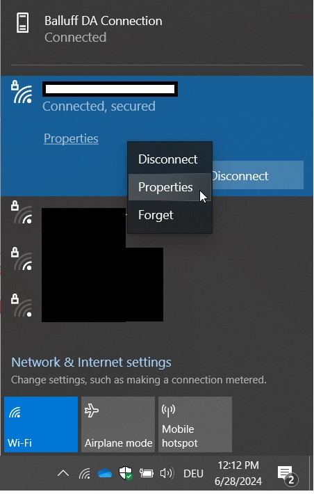
The following dialog appears:
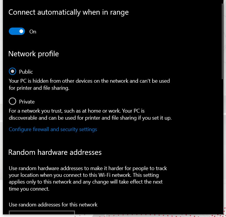
Under Network profile, activate the Public option.
What do I have to set to use USB network adapters?
If you are using a USB network adapter, you must check the adapter’s network settings. The topology to be scanned and the device with the BET application must be in the same network and in the same IP range.
Example 1 IP range of the machine network to be scanned:192.168.0.x Possible network address of the PC in the range: 192.168.0. 2…254
Note
The last number must not be 0 or 255, because these IP numbers have special meanings.
Example 2 IP range of the machine network to be scanned:10.0.x.y Possible network address of the PC in the range: 10.0.x.z (with z = 2…254)
To set the USB network adapter:
Note
These settings of the firewall can only be made with administrator rights. If you cannot change these settings with your rights, we recommend contacting the IT service.
Click the Windows Start menu, search for Preferences, and click Open.
Select Network and Internet > Statuts > Change adapter options.
The following dialog appears:

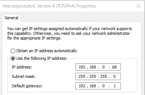
Assuming that the topology to be scanned is located in the private network 192.168.x.x, assign an IP address in the same IP range (192.168.0.1…192.168.0.254) to the Windows USB network adapter.
Make sure that a default gateway has been defined for the adapter:
Note
If the scan does not work properly, it may also be due to the installed driver of the network adapter.
To check if the installed device driver is up to date:
Note
These settings of the firewall can only be made with administrator rights. If you cannot change these settings with your rights, we recommend contacting the IT service.
Click the Windows Start menu, search for Show Network Connections, and click Open.
Double-click the desired network adapter.
The following dialog appears:
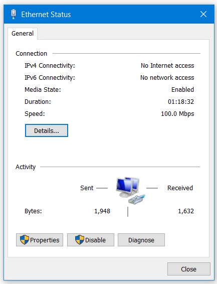
Select Properties.
The following dialog appears:
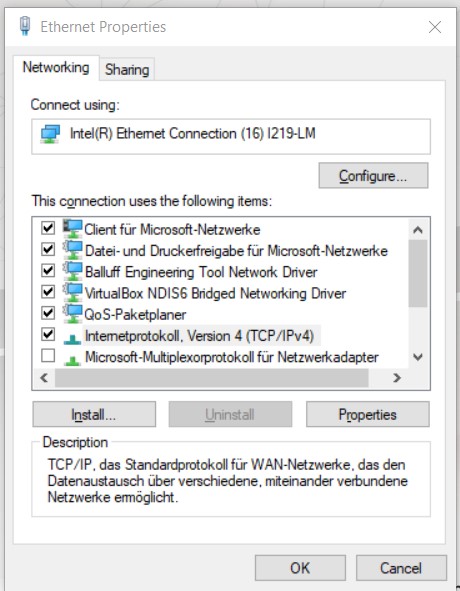
Select Configure > Driver.
The following dialog appears:
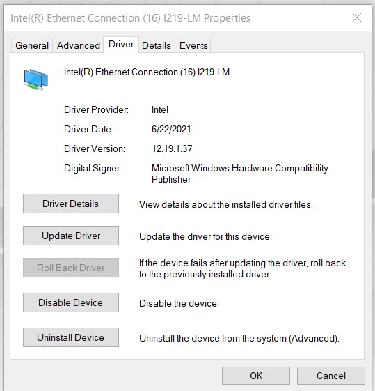
5.click Update Driver.
Find scan/device FAQ
Why are not all IO-Link network modules found during the scan process?
The following options are available:
Use a compatible USB-AN-ETHERNET ADAPTER, e.g. Syncwire USB 3.0 to RJ45 Gigabit Ethernet Adapter.
Use a USB TO ETHERNET ADAPTERS: Check the adapter settings via command line (ipconfig) to ensure the following points:
The adapter must not be assigned two IP addresses.
The IP address of the adapter must be unique in the network.
A default gateway is defined.
The current drivers are installed.
The network adapter of the PC to be scanned is not connected to an IO-Link network module. Check whether the web server of the IO-Link network module can be accessed by entering the IP address of the IO-Link network module in the address line of the browser. If this succeeds, check points 4 and 6.
The IP address of the IO-Link network module is outside the IP address range of the network adapter being scanned. The IP address range must match except for the last number.
Example: Master IP: 192.168.0.111, adapter address range: 192.168.0.1 - 192.168.0.254 Further information can be found in the question about the USB To Ethernet Adapter
The following ports should not be assigned by another application:
2000 (incoming) and 1999 (outgoing) for UDP and 2222 (incoming) for UDP at CIP.
44818 for Ethernet/IP CIP (outgoing)
The address of the network adapter may have been changed during operation of BET . If this is the case, switch to the “Main view” and start a search again so that the adapter is recognized again.
The problem may be that a virtual network adapter has been installed on the computer, which has the same network setting. In this case, the following actions can solve the problem:
Disabling the virtual adapter
Change IP address ranges of the virtual network adapter so that they differ from address ranges of the other network adapters.
Note
We recommend connecting the BET PC to the topology via a network cable. The topology is not always recognized reliably via a WLAN connection.
Note
The BET can only scan topologies that are in the same address range as the network adapter of the PC itself. Scanning across a gateway address is not possible. Therefore, no router must be connected in between.
If only one GENERIC IO-LINK MASTER is detected during the scan, the IOLM of the corresponding master must first be imported so that its functionality can be used.
If the Balluff IO-Link device manager is open at the same time as BET , the device manager must be closed and the BET restarted.
Why can’t I find any IO-Link devices during the scan process?
There are 2 possibilities: **No device is detected on the port.
Check the port settings on the IO-Link network module.
Perform a scan with the option Perform unlocking of all IO-Link ports.
If the scanned IO-Link network module is a REST API device and you click the UNLOCK ALL IO-LINK PORTS option during the scan process, connected IO-Link devices are only displayed if you log in to the IO-Link network module in the following step:
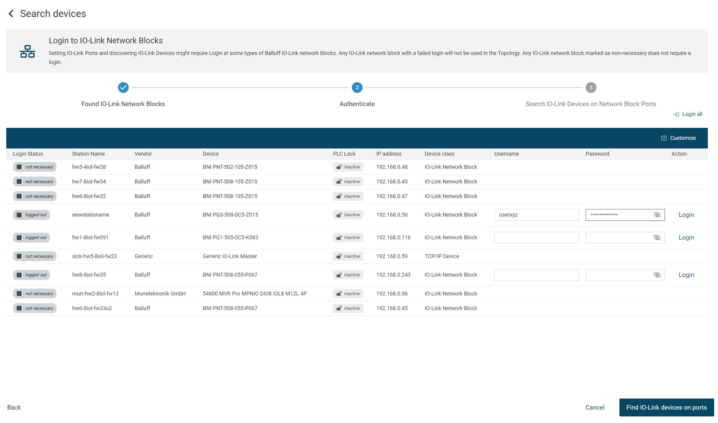
**A Generic IO-Link Device is detected at the port.
Complete the scan normally and add all devices to the topology.
Switch to the “Topology editing” view and load the IODD associated with the device into BET, see Import device description files.
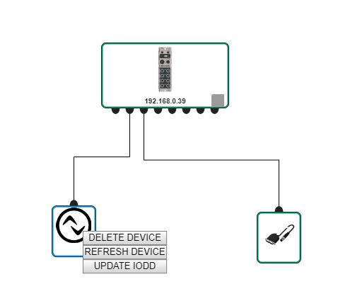
Switch to the main view, right-click the IO-Link device and select Update IODD.
If a scan with the Execute all IO-Link ports option also fails to find a device and the port to which the IO-Link device is connected does not light up green, then check the connection of the IO-Link device to both the hardware of the device and that of the IO-Link network module.
How long can a scan take and when is it finished?
Scanning the network topology can take up to 10 seconds per IO-Link network module. So if you scan a network with 10 IO-Link network modules, the duration of the scan can be in the range of up to 100 seconds or almost 2 minutes.
If the time that can be determined using this rule of thumb is far exceeded in your application without the scan dialog indicating a problem, restart BET .
Why are not all IO-Link devices installed in the field displayed after a scan in the topology?
If an error is displayed during the scan, please check the log and see the responses for network connection problems and UDP. If no error is displayed and devices are found on some ports of the IO-Link network modules, but not all of them, then it may be because the scan with the Enable all IO-Link ports option was not applied correctly.
Solution: Keep the current topology. Scan the topology again, this time without selecting the Enable all IO-Link ports option. Add the newly found devices to the topology.
Why can I add only a limited number of network modules to the topology?
The number of IO-Link network modules that can be processed simultaneously in a topology is limited to 50.
Why are one or more IO-Link devices displayed in the topology as “Generic IO-Link Device”?
The BET shows you IO-Link devices as “Generic IO-Link Device” if no IODD matching this device is available in the internal device catalog. An IODD is suitable for its device if all of the following features match both in the device and in the IODD:
Vendor ID
Product ID
Device ID
IO-Link version
If the data does not match in at least one characteristic, then the device is displayed as a Generic device.
Solution: To make a generic device usable, you need the IODD that matches the device in all 4 parameters. To do this, call up the context menu for the device in the topology and click on UPDATE IODD. The system searches online for the device description files (IODD) and then updates the devices.
Why can’t I update the IODDs of the devices?
When automatically updating the IODDs via the context menu of the IO-Link devices, the following error messages may occur:
3008-Error - Balluff Engineering Tool is offline
Solution: Check if they have a connection to the internet.404-Error - IODD file not found
This error occurs when no IODD exists in the IODD Finder for the IO-Link device being searched for.
Solution: In this case, try contacting the manufacturer of your IO-Link device.
Why are some IO Link devices displayed as “Disconnected” in the topology after I have parameterized a device?
After switching from the view of an IO-Link device or the IO check, it is possible that an IO-Link device is suddenly shown as disconnected with a red X. This is a display error.
Solution: Click Update at the top right of the main view to fix the display error.
How do I write parameters to the IO-Link devices on a REST API IO-Link network module?
Solution: If you have made your changes and click Write, you can only write your changes to the device after logging on to the IO-Link network module.
Why can’t I write the process data on an IO-Link device?
Writing process data is prevented by BET as long as a PLC is connected to the network module to which the IO Link device is connected. The BET signals this status by displaying a symbol with a closed lock in the device view. In the event that the PLC was disconnected from the IO-Link network module while it was in operation, the IO-Link network module may not automatically update the change in PLC connection status. In this case, BET displays an open lock in the device view.
Solution: Restart the IO-Link network module without it being connected to the PLC at startup.
Why does a change in the process data of a BNI IOL Sensor/Actuator Hub lead to no change in the device?
For correct functioning of the BNI IOL sensor/actuator hubs, it is necessary that the hub is supplied with “actuator voltage”. You can switch this on as follows:
Double-click the IO-Link network module to which the hub is connected.
The detailed view of the IO-Link network module opens. 2. Open the PORT CONFIGURATION tab.
Select Digital output for pin 2 of the port.
Click SET, and click BACK.
Click I/O-CHECK in the function bar.
Select the IO-Link network module that is connected to the hub.
Select SET under I/O control for pin 2 of the port.

Double-click the BNI sensor/actuator hub in the topology.
The detailed view of the device opens. Open the PARAMETERS tab. 10. Check the parameter that provides information about “Actuator Voltage (UA)”.

Note
Depending on the IO-Link device, this parameter may have a different name.
If the actuator voltage is switched on but writing is not possible, the cause may be that the IO-Link network module has not updated the PLC connection status.
Why are no units (e.g. °C) displayed on the process data?
IODDs with IO-Link version 1.0 do not provide for units and formatting of the process data. Therefore, the BET has no information for a more precise representation of the unit.
Why don’t I see any data about the device in the Diagnostics/Observation tab?
The IODD for this device contains process data that is mapped as ISDU parameters. However, the process data is only displayed in BET within the Process data tab. This is because the interface for the device is automatically created from the IODD. It is therefore possible that no data is displayed in the Diagnostics/Observation tab.
Why don’t I see any entries in the LOG of BET ?
The log has 2 modes: either display all entries or display only the entries for one device. If the log is currently displaying the entries for a device, but no entries exist for this device, the log is without entries.
SOLUTION Exit the log. The selected device is outlined in blue. To deselect all devices, click on a free area in the main view.
How can I uninstall BET ?
Right-click on the desktop shortcut of BET and select Open file path.
Run Uninstall Balluff Engineering Tool.exe.
When installing a version prior to 1.61, it is recommended to completely uninstall the previously installed version of BET via the Control Panel, as otherwise problems may occur. These can manifest themselves in the form of error messages when starting the application or in the application not working properly. From version 1.61, the problem is already avoided as the uninstallation is carried out properly.
Solution
Uninstall via the Start menu:
Select Start
and search for Balluff Engineering Tool in the list that appears.
Right-click on it and then select Uninstall. A window opens with the programs that you can uninstall. Select Balluff Engineering Tool X.Y.Z in the list and click “Uninstall” in the top bar.

Geben Sie in der Adressleiste Ihres Dateiexplorers “C:\Users\[Ihr Benutzername]\AppData\Local\Programs” ein (Laufwerkbuchstabe C: kann je nach Installation des Betriebssystems variieren). Löschen sie die Ordner “Balluff Engineering Tool” und “BET_DB”.
You can then install your new version of BET .
What to do if the administrator password is forgotten?
If the administrator password needs to be reset, contact Balluff support.
FAQ about the configuration of the devices
Why can’t I use network settings to change IP numbers of Ethernet IP IO-Link network modules?
Network settings cannot be used to change IP numbers of Ethernet IP IO-Link network modules.
Solution: Change the IP number of the Ethernet IP IO-Link network module via the web interface within the Ethernet IP IO-Link network module and restart the Ethernet IP IO-Link network module. After restarting the Ethernet IP IO-Link network module, delete the representation of the Ethernet IP IO-Link network module with the old IP number from the topology. Scan the topology again and add the Ethernet IP IO-Link network module with the new IP number again.
IO-Link network modules show fewer ports in BET than in reality.
The BET can only display the ports that can be switched to IO-Link. Any port that cannot be switched to IO-Link cannot be visualized.
How do I activate the extension port on an IO-Link hub so that I can operate 2 hubs in a daisy chain?
If the hubs drive output ports, the PIN 2 of the port on the IO-Link must be set to Digital Output to ensure smooth operation. Proceed as follows here:
Set pin 2 of the IO-Link port to which the sensor hub is connected to Digital Output.
Go to IO Check and activate the Digital Output.
Proceed as follows for activation and correct display in BET :
Go to Device Details and set the Extension Port parameter. If it does not appear in the parameter list: Go to the ISDU Parameter tab and set the parameter with index 85 subindex 0 to the appropriate setting.
click on update
a mismatch is detected, the device identity of the device has changed.
Switch to the topology view and click Update IODD in the context menu of the device.
Why are the parameters and settings not saved during topology export?
Parameters and settings made on devices that are not connected to an IO-Link network module are not saved when exporting a topology.
The BNI web interface shows more port parameters than the BET port options menu.
Some of the IO-Link network modules offer more port configuration options within the web interface panel than in the port configuration panel of BET. The reason for this is that these settings cannot be retrieved from the network module via the current interface of BET .
Workaround: Log into the web interface of the IO-Link network module to configure these additional port parameters.
FAQ about importing the device list into the Balluff shopping cart
How do I import the device list into the Balluff shopping cart?
In a web browser, open www.balluff.com.
The Balluff web page is loaded.

Click Shopping Cart.
The shopping cart is loaded.
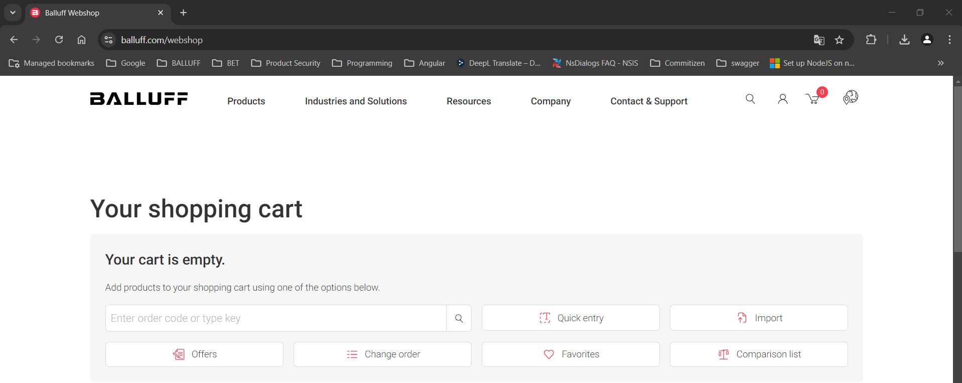
Click Import.
The following page is loaded.
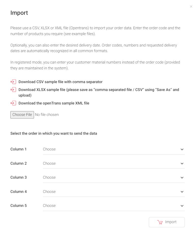
Click Select file, select the device list you want to import, and click Open.
In columns 1-5, enter additional information about your order, such as the quantity or the order code.
Click Import.
The device list is imported into the Balluff shopping cart. If devices cannot be obtained via the Balluff shopping cart, a message appears:
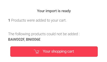
All available devices are displayed in the Balluff shopping cart and can be ordered:
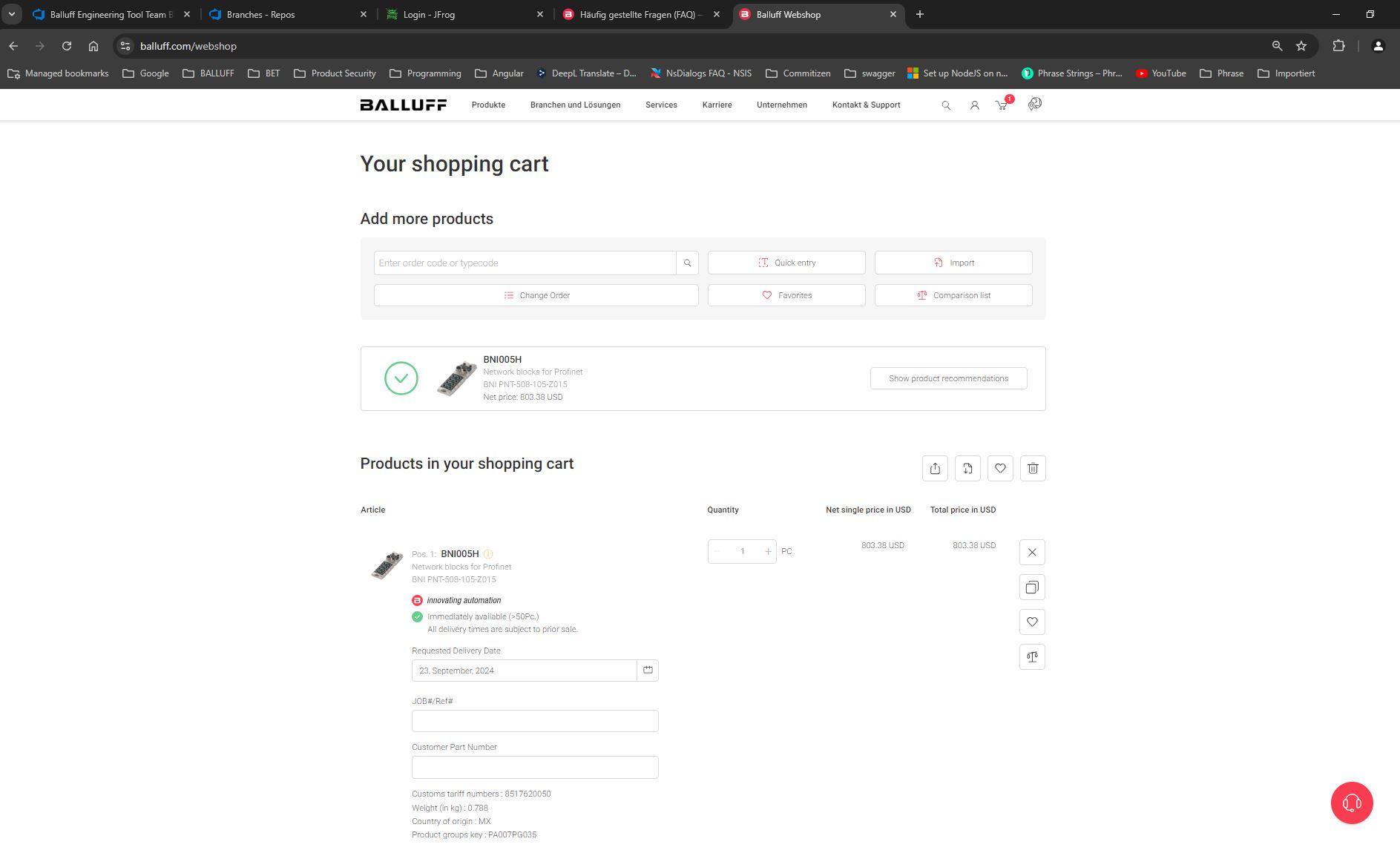
FAQ for updating the firmware
Why can’t I update the firmware of my IO-Link device?
The FIRMWARE UPDATE function works exclusively for Balluff-IO-Link devices.