View and edit device details
Jul 24, 2026 | 3879 words | 19 min reading time
The detailed view allows you to have closer control and overview of specific devices. In this view, you can set parameters and perform diagnostics. The detail view changes dynamically depending on which device category is called up. The main differences are between IO-Link network modules and IO-Link devices. Depending on the user role and the status of the PLC, you can change parameters on the IO-Link device or network module.
Overview of network module details
Pos. |
Description |
|---|---|
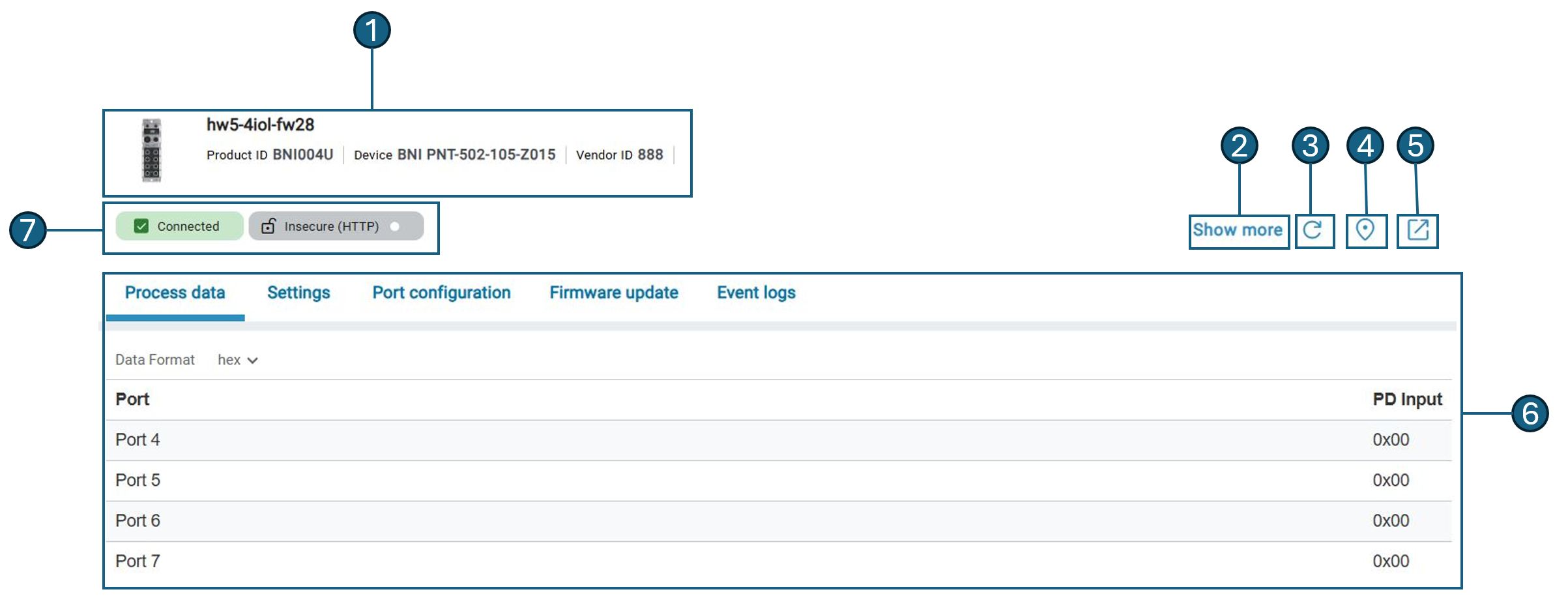
1 |
Shows the most important information for identifying the network module: |
2 |
Shows further network module details. |
3 |
Updates the display of the device details. |
4 |
Makes the LEDs of the network module flash for easy identification. |
5 |
Opens the web interface in the browser. |
6 |
Display area of the device details. |
7 |
Shows the status of the connections. |
Overview device details
Pos. |
Description |
|---|---|
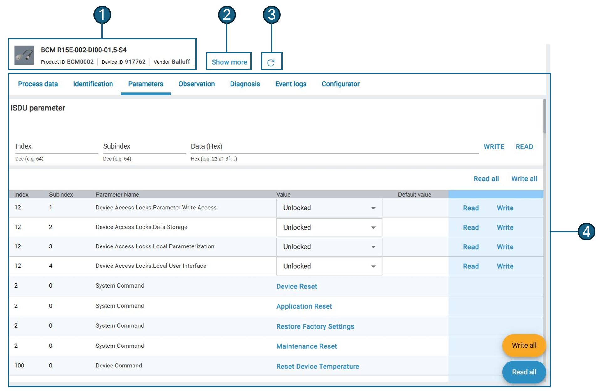
1 |
Shows the most important information for identifying the device: |
2 |
Shows further device details. |
3 |
Updates the display of the device details. |
4 |
Display area of the device details. |
General operation
Show detail view
Click Topology in the function bar.
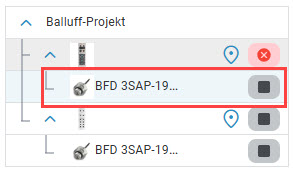
Under Balluff project, select the network module or the device whose details you would like to view.
The detailed view of the desired network module or device is displayed.
Update detail view
Open the detailed view and click  .
.
The status of the devices is updated.
Note
The BET does not automatically update the device status in the detailed view. The displayed status may therefore differ from the actual status.
Edit IO-Link network modules
In the detailed view for IO-Link network modules, you can call up the web server, a process data overview and the port configuration.
Display web interface of IO-Link network modules
The web server accesses the main interface of the IO-Link network module and displays it at BET . You can operate it as usual.
Click Topology in the function bar.
To call up the details of a network module, click
 .
.
The detailed view of the network module is displayed.
Click
 .
.
The web interface of the IO-Link network module is displayed:
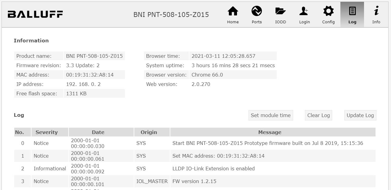
Web server
Note
Depending on the IO-Link network module and the firmware version of the device, the web interface may differ from the representation shown here. A web interface may not be available for IO-Link network modules from other manufacturers.
Edit the IO-Link network module. For more information on the web server, refer to the user documentation of the IO-Link network module.
Display process data from IO-Link network modules
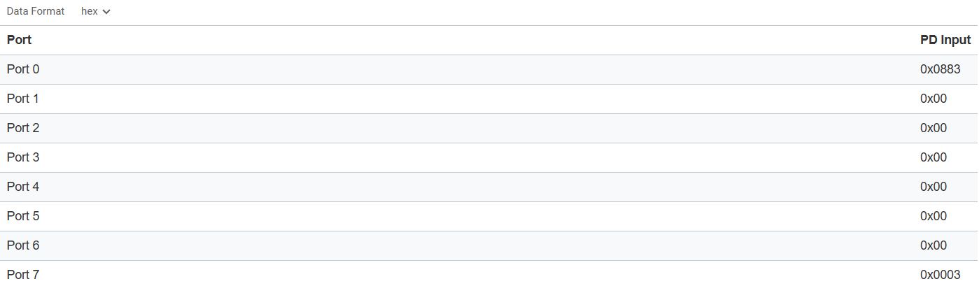
In the process data overview, all current input process data of all ports of the IO-Link network module are displayed. The detailed view is updated every 0.5 second. You can select the formats hexadecimal, decimal or binary for the display of the process data.
Click Topology in the function bar.
The detailed view of the network module is displayed.
Open the PROCESS DATA tab.
The process data of the IO-Link network module are displayed:
Configuring ports of IO-Link network modules
You can configure individual ports in the Port configuration view.
Warning
ACCIDENTAL DANGER! Changing the port status can lead to a change in the electrical signals of the IO-Link network module and to the termination of communication with IO-Link devices. It must be ensured that no accidents or damage can be caused by changing the ports. If this cannot be ruled out, the function must not be used.
Note
The ports in the IO-Link network module are only changed if the IO-Link network modules are not connected to a PLC.
Click Topology in the function bar.
The detailed view of the network module is displayed.
Open the Port configuration tab.
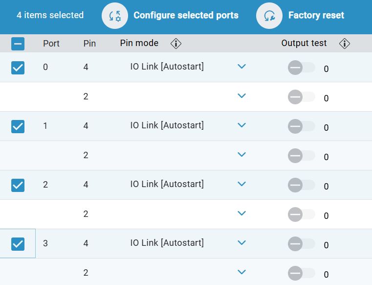
The current port configuration of the IO-Link network module is displayed:
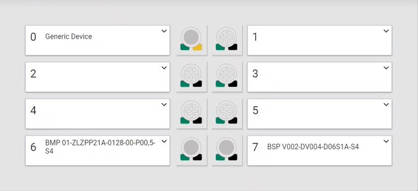
Note
Click on  next to the column headings to display further information on these setting options.
To configure a port, click on the right-hand side of the respective pin mode set
 .
.
The port configuration is displayed:
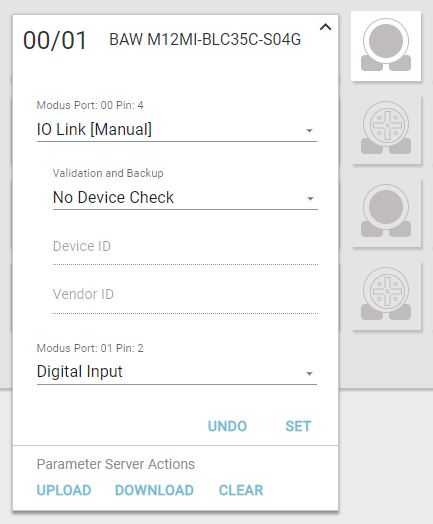
In the port configuration, select an IO-Link mode for each pin:4 of the port:
IO Link [Autostart]: The port is automatically in IO-Link communication.
IO Link [Manual]: The port can be set up manually for IO-Link communication.
Digital Input: Port behaves like a digital input.
Digital Output: Port behaves like a digital output.
Note
Depending on which pin was selected for the configuration, different options can be displayed.
Note
Depending on the settings made, options for further settings are enabled.
Perform advanced port configuration of IO-Link network modules
To carry out an extended port configuration for certain ports or to configure several ports at the same time, activate
 in front of the desired ports.
Click on Configure selected ports in the top bar.

The following dialog for port configuration is displayed:
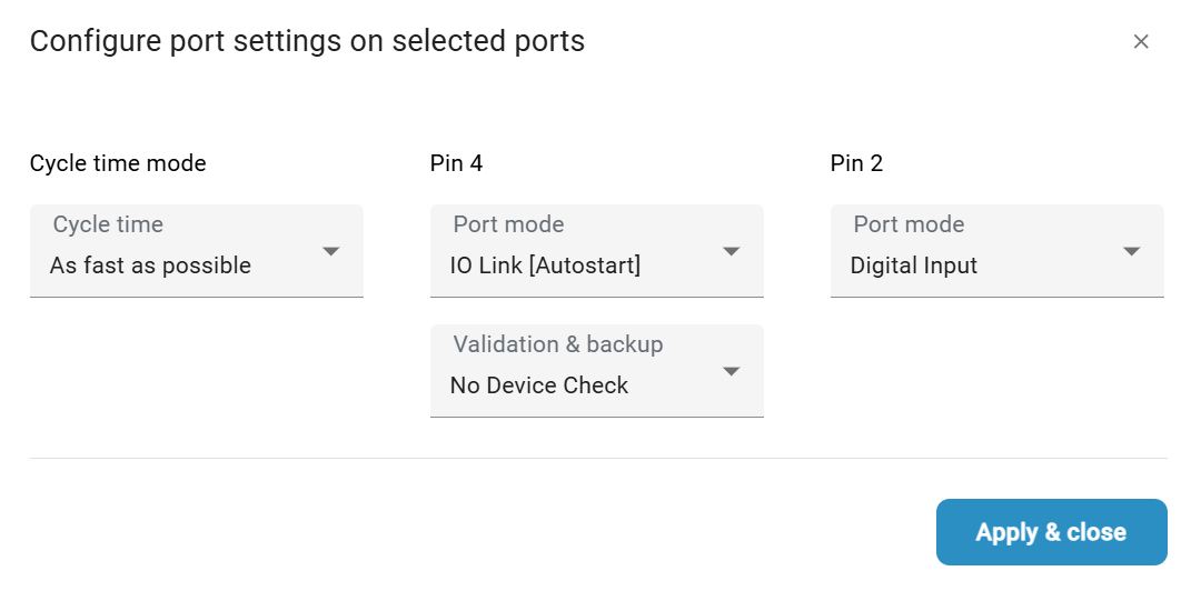
If you have selected the port mode IO Link [Manual] for ports 2/4, select the desired option in the drop-down menu Validation and backup:
No Device Check: No validation of the connected IO-Link device and no backup of the parameter values of the IO-Link device.
V1.0 Compatible: For IO-Link devices that are compatible with the IO-Link standard V1.0. Validation of whether it is an IO-Link device of the same type (using the manufacturer ID and the device ID). No backup of the parameter values of the IO-Link device.
V1.1 Compatible: For IO-Link devices that are compatible with the IO-Link standard V1.1. Validation of whether it is an IO-Link device of the same type (using the manufacturer ID and the device ID). No backup of the parameter values of the IO-Link device.
V1.1 Backup and Restore: For IO-Link devices that are compatible with the IO-Link standard V1.1. Validation of whether it is an IO-Link device of the same type (using the manufacturer ID and the device ID). Saving the parameter values of the connected IO-Link device in the IO-Link network module. Changes to the parameter values are also saved. When an IO-Link device with factory settings is connected, the parameter values saved in the IO-Link network module are automatically restored in the IO-Link device.
V1.1 Restore: For IO-Link devices that are compatible with the IO-Link standard V1.1. Validation of whether it is an IO-Link device of the same type (using the manufacturer ID and the device ID). No saving of changes to the parameter values of the connected IO-Link device in the IO-Link network module.
If an IO-Link device is replaced on a port set in this way, the parameter values saved in the IO-Link module are written to the newly connected IO-Link device with factory settings. If you have selected the IO Link [Manual] port mode, enter a device ID and a vendor ID.
Cycle time mode: You can enter the cycle time for reading the inputs here.
Note
In controllers, the cycle time is the time needed to read the inputs, run the program, and update the outputs. In communication systems, the cycle time is the time it takes for all devices to exchange their data before the next cycle begins. For IO-Link, this time depends on the transmission rate.
Click Apply & close to apply your changes or close the dialog with
 to discard your changes.
The following dialog for confirmation is displayed:
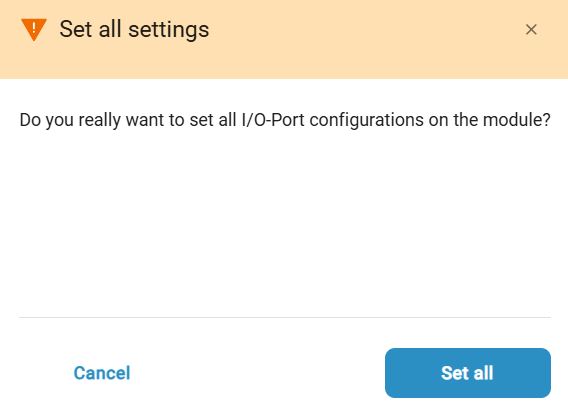
To save your changes, click on Save changes in the main window for the port configuration. To undo them, click on Discard changes.

Factory reset
You can also reset the port configuration of your network module to the factory settings.
Click Topology in the function bar.
The detailed view of the network module is displayed.
Open the Port configuration tab.
The current port configuration of the IO-Link network module is displayed:
Select the ports that you want to reset to the factory settings. To do this, activate
in front of the desired ports.
Click Reset to factory settings.

The port configuration for the selected ports is reset to the factory settings.
Set IO-Link network module
In the Settings view, you can change, load and save the IO-Link network module settings.
Click Topology in the function bar.
To call up the details of a network module, click
.
The detailed view of the network module is displayed.
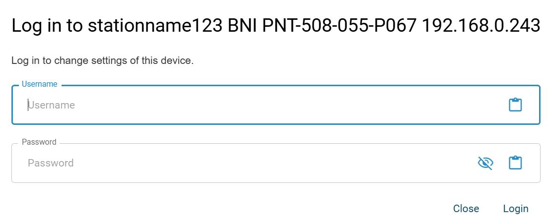
Note
If the selected module requires authentication, you will be prompted to do so. A dialog is displayed in which you can enter your user name and password for the device.
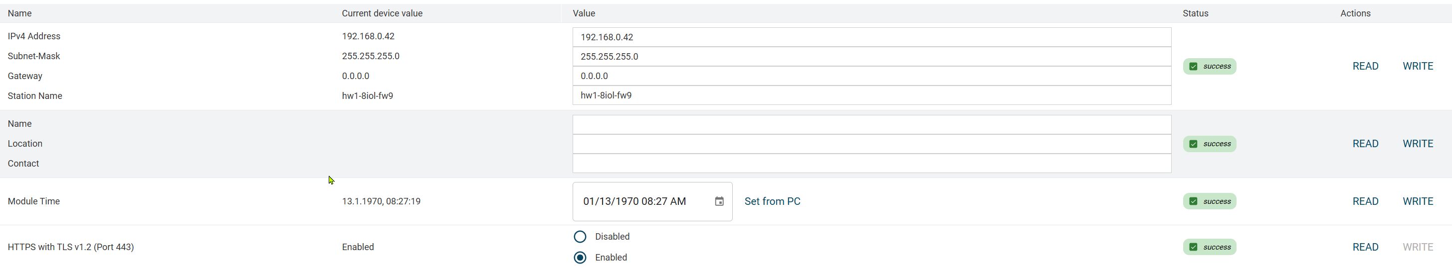
Open the Settings tab.
The tab with the settings for the IO-Link network module is displayed:
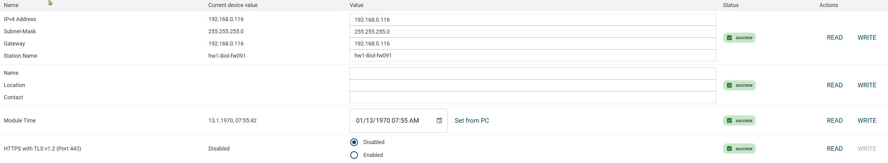
Change the desired setting.
To apply the changed setting to the IO-Link network module, click WRITE.
Activate HTTPS mode for IO-Link network modules
To activate HTTPS mode for an IO-Link network module, proceed as follows.
Click Topology in the function bar.
To call up the details of a network module, click
.
The detailed view of the network module is displayed.
Open the Settings tab.
The IO-Link network module settings tab is displayed:
Click the Enabled option.
The following dialog appears:
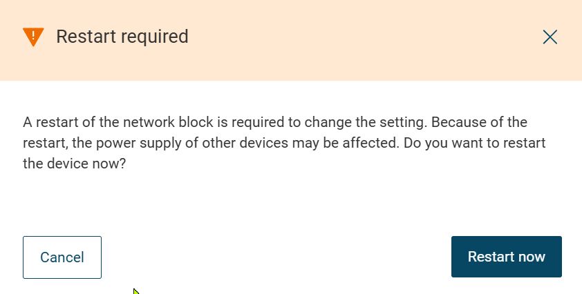
Click Restart now.
HTTPS mode is activated and the IO-Link network module is accessible via HTTPS (port 443).
Note
You can also see the status of the HTTPS mode in the sidebar. Click here:

The status of the HTTPS mode is displayed.
Deactivate HTTPS mode for IO-Link network modules
To deactivate the HTTPS mode for an IO-Link network module, proceed as follows.
Click Topology in the function bar.
To call up the details of a network module, click
.
The detailed view of the network module is displayed.
Open the Settings tab.
The IO-Link network module settings tab is displayed:
Click the Deactivated option.
The following dialog appears:
Click Restart now.
HTTPS mode is deactivated and the IO-Link network module can be reached via HTTP (port 80).
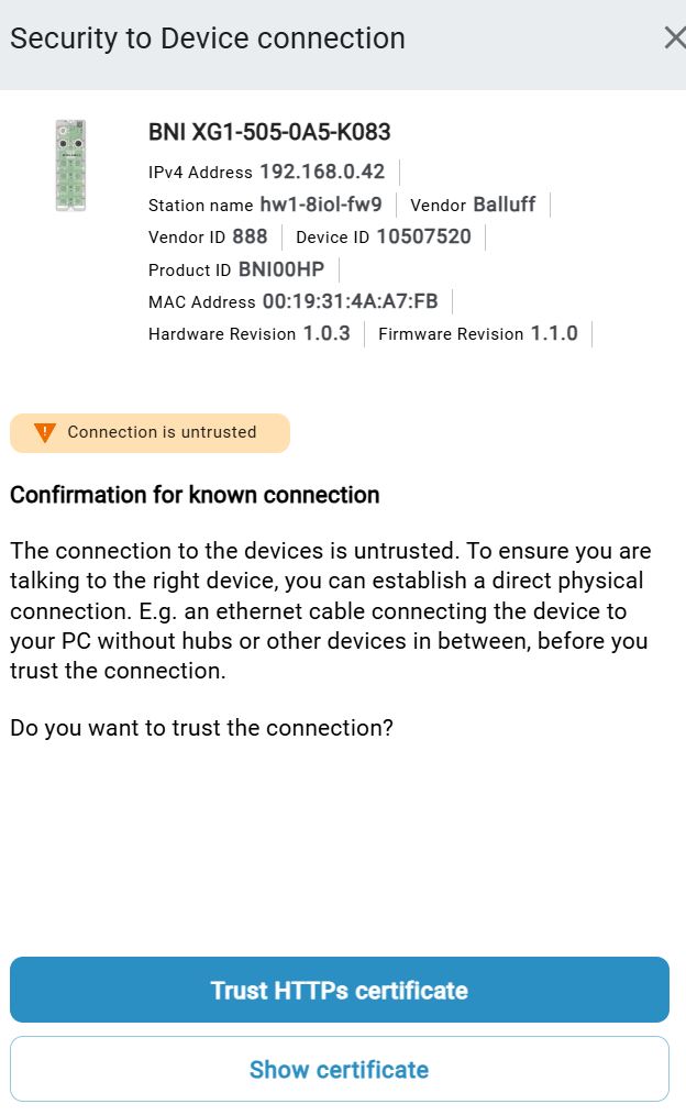
Trust HTTPs certificate
The trustworthiness of the connection to the connected IO-Link network module must be attested by the HTTPS certificate for unknown connections.
Click Topology in the function bar.
To call up the details of a network module, click
.
The detailed view of the network module is displayed.
Open the Settings tab.
The IO-Link network module settings tab is displayed:
Click on Details in the button for the HTTPS status.
The following dialog appears for untrusted connections:
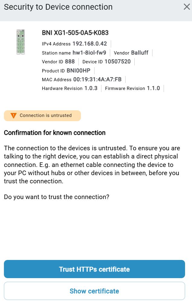
To trust the certificate, click HTTPS certificate trust.
The HTTPS connection to the IO-Link network module is trusted.
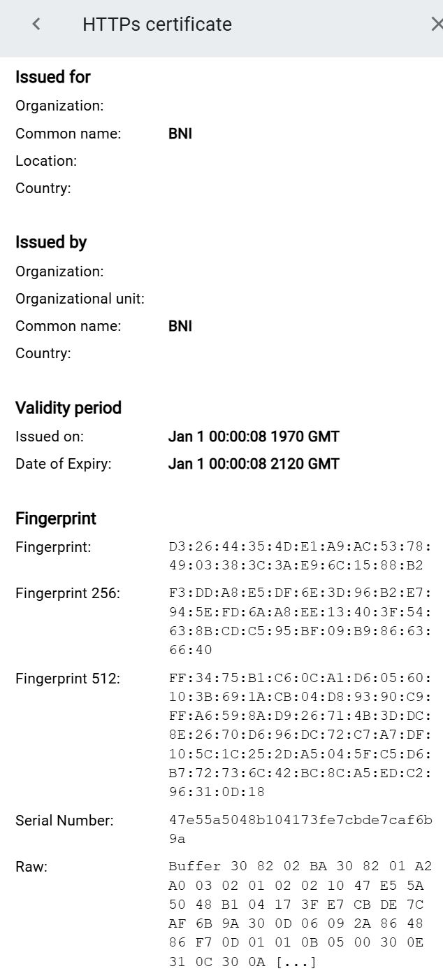
Show HTTPS certificate
You can display information about the certificate, such as the validity period of the certificate.
Click Topology in the function bar.
To call up the details of a network module, click
.
The detailed view of the network module is displayed.
Open the Settings tab.
The IO-Link network module settings tab is displayed:
Click on Details in the button for the HTTPS status.
To display the certificate, click Display certificate.
The certificate is displayed:
Edit devices
In the detail view for devices you can edit the following data:
Device parameters
PROCESS DATA
ISDU-Parameter
Note
Depending on the IO-Link device, other data can also be displayed, e.g. diagnostic information, observations or a configurator.
Parameterize devices
The parameters displayed depend on the respective device description file. Details on the individual parameters can be found in the user documentation of the devices. Parameters for which the WRITE option is present can be written to the physical device.
Show device parameters
For the IDENTIFICATION, PARAMETERS and PROCESS DATA tabs, you can filter the amount of information displayed.
Click Topology in the function bar.
Select the desired device under Balluff project.
The detailed view for the selected device is displayed.
Open the Parameters tab.
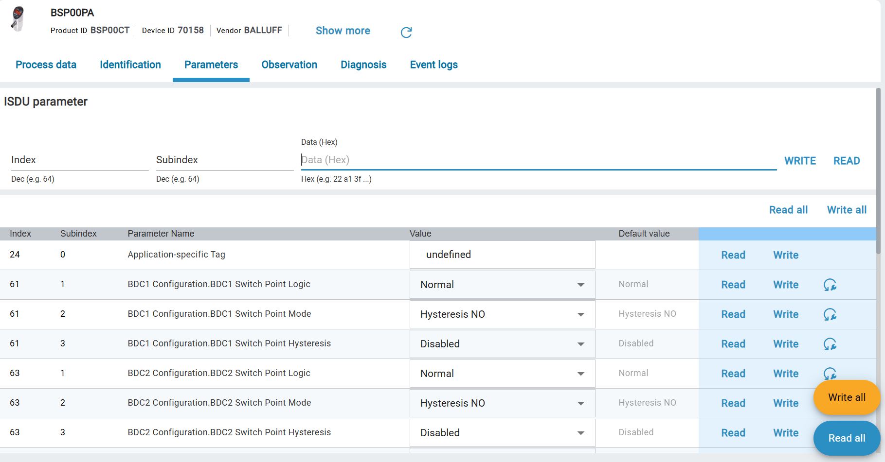
Example: PARAMETERS tab
Set device parameters
Device description files (IODDs) specify to BET how the parameters are displayed and whether the parameters may be changed. Further information on the effects of the parameter settings can be found in the operating instructions for the corresponding devices.
If you change a parameter, this is indicated by a changed device status. The status of the parameter is displayed with symbols to the right of the parameter name field. The device status is only updated if you write changes to the physical device or read the device parameter from the device.
The following device statuses are possible:
Symbol |
Status |
Description |
|---|---|---|
Without |
Parameter: |
The displayed parameter value is the default value |
|
Parameter: |
The displayed parameter was successfully |
|
Parameters changed |
The value has been changed, |
|
Parameters: |
An error occurred |


Click Topology in the function bar.
Select the desired device under Balluff project.
The detailed view for the selected device is displayed.
Open the Parameters tab.
The parameters of the IO-Link device are displayed.
Change the desired parameter. You can only change the parameters for which the WRITE function is available.
The parameter is changed and marked with a  symbol.
Click WRITE to transfer the changed value to the physical device.
Load parameters from device
You can overwrite the configured parameter values with the current parameter values from the physical device. You have the option of selecting whether all or only certain parameters should be overwritten for the configured device.
Select the desired IO-Link device in the topology and click on the Parameters tab.
The detail view appears in the workspace.
Select READ or Read all.
The parameters from the physical device are loaded into the project:
Write parameters to the device
You can overwrite the parameter values from the physical device with the parameter values from the configured device. You have the option of choosing whether all or only certain parameters should be written to the physical device.
Note
You can only execute this function if no PLC is connected, since the parameters may then not be changed.
Warning
DANGER OF ACCIDENT! By changing parameter data, switching points and data of IO-Link devices can be changed. Before resetting/writing the changes, ensure that accidents or damage cannot occur as a result of the change. The function must not be used if accidents/damage can occur as a result of reading/writing process data.
Select the desired IO-Link device in the topology and click on the Parameters tab.
The detail view appears in the workspace.
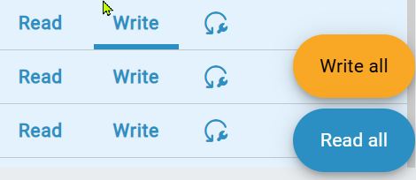
After you have made your changes, select Write or Write all.
The parameters from the configured device are overwritten with those from the physical device.
Note
If you want to restore the default values for certain parameters, click on Restore default value

SAVE PARAMETER SET
You can save the current parameter set of a device and load it into another device later. The parameter set is saved in the database of BET .
Note
Only the parameters that can be written are saved. Process data is not saved.
Select the desired IO-Link device in the topology and click on the Parameters tab.
The detailed view for the selected device appears in the work area.
Under Parameter set: click on
 .
.
The following dialog appears:
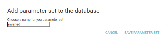
Enter a name for your parameter set. Tip: Structure the name, for example “Signallight_LvLMode”.
Click * SAVE PARAMETER SET*.
The parameter set is saved in the BET database.
Load parameter set
You can load a saved parameter set and assign it to the configured device if a parameter set has been saved for this device. The BET database shows you all parameter sets for the currently open IO-Link device.
Note
The changed parameter values of the configured device are not automatically written to the physical project.
Select the desired IO-Link device in the topology and click on the Parameters tab.
The detailed view for the selected device appears in the work area.
Under Parameter set: click on
 .
.
The following dialog appears:
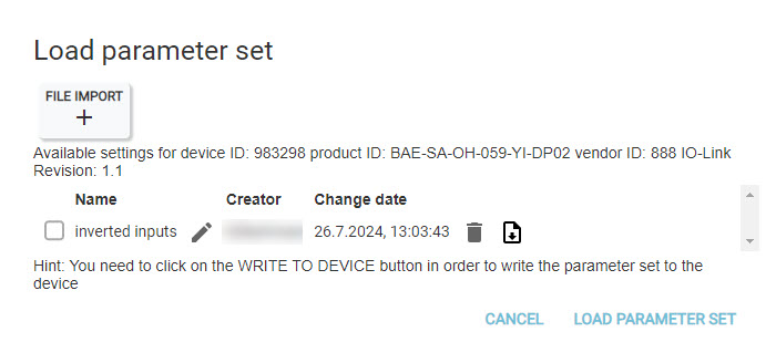
Select a parameter set or click IMPORT FILE to import a parameter set and add it to the list.
Click LOAD PARAMETER SET to load the parameter set.
Note
You have the possibility to edit the parameter set before loading, see Edit loaded parameter set.
The parameters from the configured device are compared with the parameters from the file:
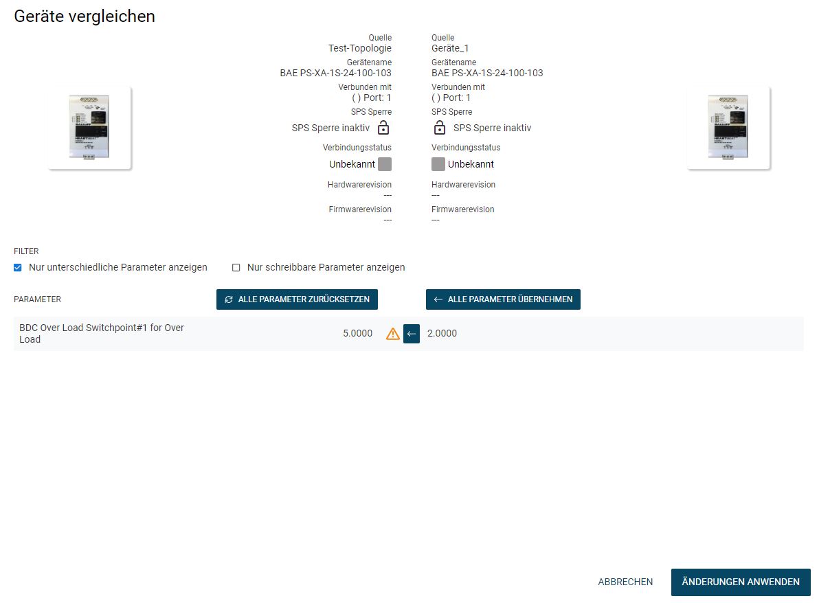
The left column shows the parameters of the projected device (source: [name of your BET project]), the right column those of the loaded file (source: [file name]).
Compare the parameter values of the configured device with the parameter values from the loaded file, see Compare device parameters with each other.
Click * APPLY CHANGES* to apply the selection of parameters to the configured device and close the view.
Compare device parameters with each other
Note
You can only compare parameters that occur in both IODDs. This is not always the case for identical devices with different IODD versions, so that in this case not all parameters can be taken over.
In the dialog Compare devices, under FILTER you can filter the parameters. You have the following options:
Display only different parameters: Identical parameter values are filtered out so that you only see the different parameter values.
Display only writable parameters. All parameters that can be changed are displayed, regardless of whether the parameter values are identical or not.
To apply all parameter values in one step, click * APPLY ALL PARAMETERS*.
All parameters of the source from the right-hand column are adopted for the parameters in the left-hand source. You can undo the change by clicking on Reset all parameters. You can also exclude individual parameters from the transfer.
To apply individual parameters, click
 .
.
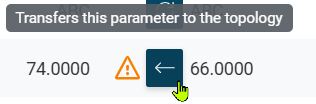
The parameter from the right-hand source is transferred to the left-hand side.
To undo the transfer of a parameter, click
 .
.

The transfer of the parameter value from the right source is reset for this parameter.
Click APPLY CHANGES to apply the parameter selection and close the view.
Edit loaded parameter set
You can edit or delete loaded parameter sets or export them as a JSON file or import them again. Parameter sets can thus be exchanged or made available to customers.
Select the required IO-Link device in the topology and click DevICE DETAILS in the function bar.
The detail view appears in the workspace.
In the function block, select LOAD PARAMETER SET.
The following dialog appears:
You have the following editing options:
Symbol |
Description |
|---|---|
|
Renames the parameter set. |
|
Deletes the parameter set. |
|
Downloads the parameter set. |


Select the desired option.
Edit process data
You can display the current process data of the device. The process data is automatically updated every 500 ms.
Warning
DANGER OF ACCIDENT! Writing process data can change electrical signals and data from sensors or trigger actuators. Before writing the process data, make sure that accidents or damage cannot occur as a result of writing the data. The function must not be used if accidents/damage can occur as a result of writing process data.
Note
The process data cannot be written if the IO-Link network module to which the IO-Link device is connected is connected to a PLC.
Display process data
Click Topology in the function bar.
Select the desired device under Balluff project.
The detailed view for the selected device is displayed.
Open the PROCESS DATA tab.
The process data of the device are displayed:

Change process data outputs
You can influence certain process data outputs if the IO-Link device currently under consideration supports this.
Under Process Data Out, select the parameter whose output you want to change from the list.
The process data is set according to your selection.
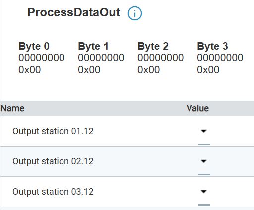
Display bytes and bits of the process data value
You can display in which bit or byte a certain process data value is contained.
Move the mouse pointer over a specific process parameter.
The corresponding byte or bit is highlighted in blue.
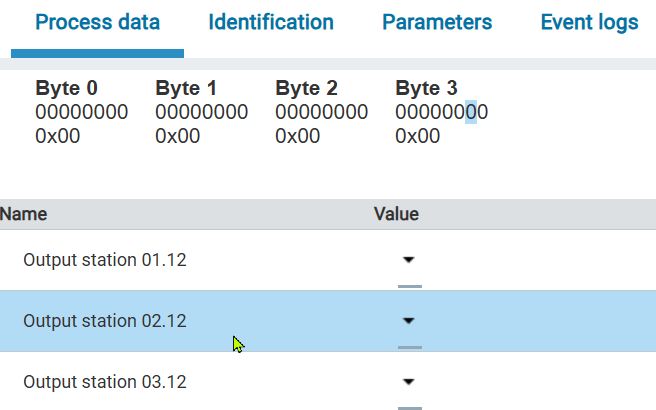
Output voltage = 00001111 (byte 0)
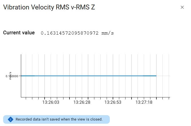
Virtualize process data
In the view, you also have the option of visualizing the process data of the selected IO-Link device in order to monitor changes live and evaluate their effects directly. To do this, click the  icon on the right-hand side of a parameter.
The corresponding parameter is visualized:
Edit ISDU parameters
ISDU is used for the acyclical transfer of parameter data. You have access to the ISDU parameters (Indexed Service Data Unit) via index and subindex. The data is displayed in raw hex format. You can also use this function for generic IO-Link devices if no IODD was found.
Click Topology in the function bar.
Select the desired device under Balluff project.
The detailed view for the selected device is displayed.
Open the Parameters tab.
The ISDU parameters of the device are displayed:
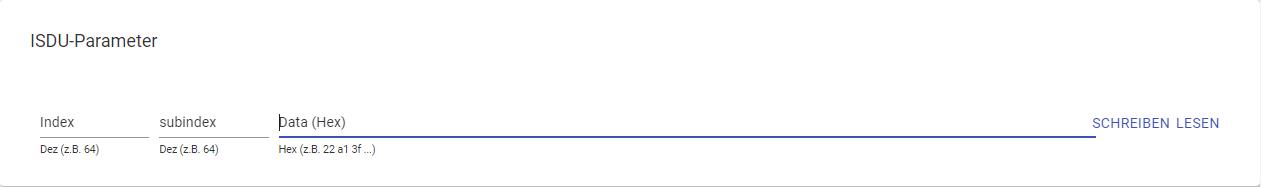
Enter a value for the index and subindex.
Click WRITE to write the values to the device or click READ to read the current parameter values.
Configure BCM devices with configurator
The BCM Configuration Wizard enables easy configuration of BCM sensors for vibration monitoring of motors, pumps, fans or compressors. In doing so, limit values for vibrations are defined depending on the power class of the aggregate and based on established ISO standards. The following BCM sensors are supported by Balluff :
BCM0001 (BCM R15E-001-DI00-01,5-S4)
BCM0002 (BCM R15E-002-DI00-01,5-S4)
BCM R16E-004-CI01-01,5-S4
BCM R16E-004-CI02-01,5-S4
The following ISO standards are applied to the aggregates:
Motors: ISO 20816-3
Pumps: ISO 10816-7
Fan: ISO 14694
Compressors: ISO 10816-3 and ISO 20816-3
If the unit to be monitored is not covered by one of the ISO standards listed, empirical values must be determined for reasonable limit values.
Note
The configurator is only available if a BCM device is physically present.
Load BCM configuration
If you have already created a BCM configuration for the sensor, you can load and edit it.
Click Topology in the function bar.
Select the desired device under Balluff project.
The detailed view for the selected device is displayed.
Open the CONFIGURATOR tab.
The BCM configurator is displayed.
To load a ready-made BCM configuration, click
 .
.
The file explorer opens.
Navigate to the desired BCM configuration file and click Open.
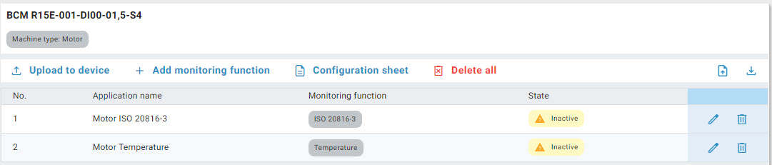
The BCM configuration with the existing monitoring functions is displayed.
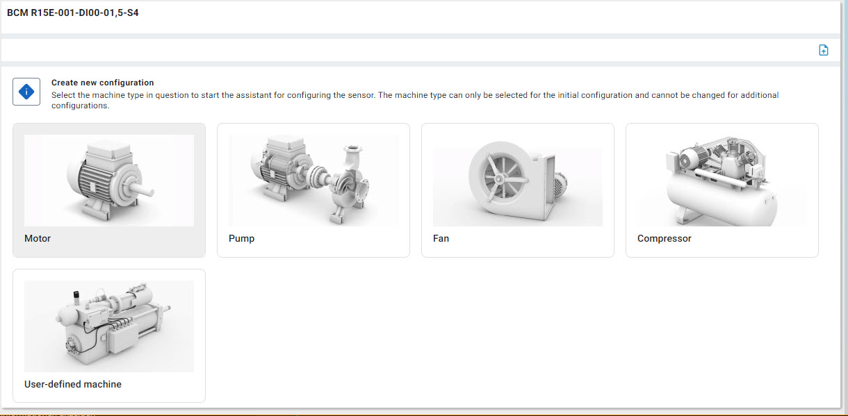
Create BCM configuration
Click Topology in the function bar.
Select the desired device under Balluff project.
The detailed view for the selected device is displayed.
Open the CONFIGURATOR tab.
The BCM configurator is displayed.
To create a new configuration, select the machine type to be monitored.
The configuration wizard for the machine type to be monitored is started:
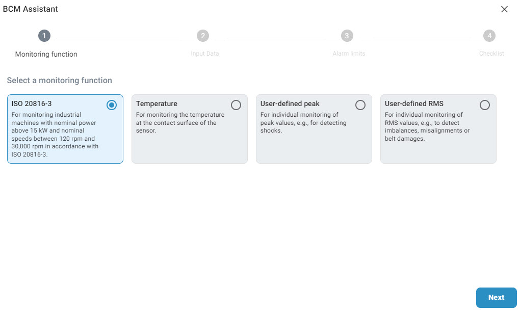
Step 1: Monitoring function (example: “ISO 20816-3”)
Select the monitoring function and click Next.
Select the input data. For the “Motor” machine type, these are the following:
Power class
Axle height
Speed range
Substructure
Alignment of the axis of rotation
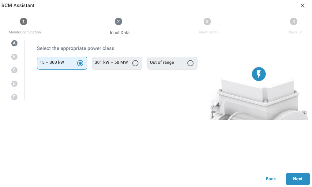
Click NEXT.
The “Alarm limits” step is displayed. The preselected threshold values for the vibrations according to the respective ISO standard are displayed here. You can still adjust these individually to your requirements.
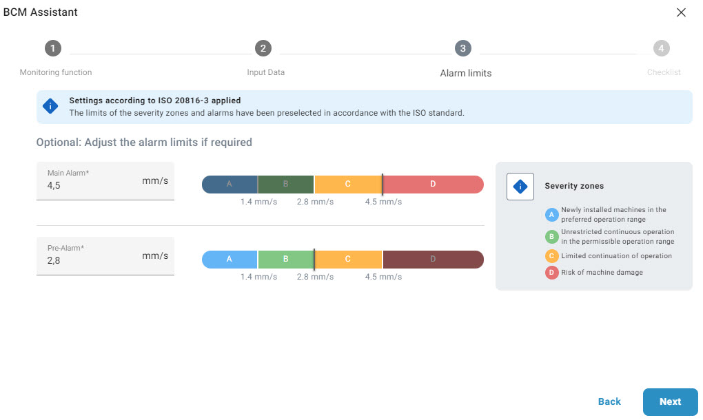
Set the desired limits and click NEXT.
The monitoring function is fully configured.
Assign a name for the monitoring function.
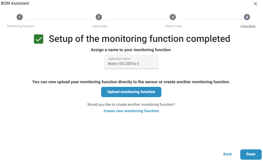
To upload the monitoring function directly to the sensor, click Upload monitoring function.
To create a new monitoring function, click Create new monitoring function.
To exit the configurator, click Done.
Upload BCM configuration to devices
Load the BCM configuration, see Load BCM configuration.
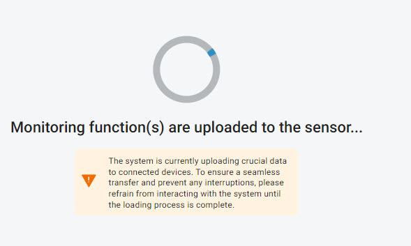
Click Upload to device.
The monitoring functions are uploaded to the devices.
Add BCM configuration
You can add up to 3 monitoring functions per BCM configuration.
Load the BCM configuration, see Load BCM configuration.
Click Add monitoring function.
The configuration wizard for the machine type to be monitored is started.
Create the monitoring function, see Create BCM configuration, from step 4.
Delete monitoring functions of a BCM configuration
You can delete one or all monitoring functions of a BCM configuration:
Load the BCM configuration, see Load BCM configuration.
To delete a monitoring function, click
 .
.
The following warning message appears.
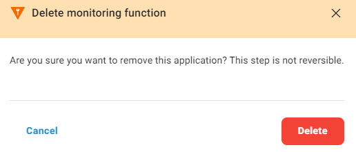
Click Delete.
The monitoring function is deleted.
To delete all existing monitoring functions in one step, click Delete all.
The following warning message appears.
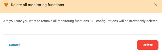
Click Delete.
All monitoring functions are deleted.
Download BCM configuration
Load the BCM configuration, see Load BCM configuration.
Click
 .
.
The file explorer opens.
Specify a file name, navigate to the desired location, and click Save.
The BCM configuration is saved as a file.
Print BCM configuration
Load the BCM configuration, see Load BCM configuration.
Click Configuration view.
The Windows print dialog opens.
Select the desired print settings.
A document with the BCM configuration settings is created and printed.
Edit BCM configuration
Load the BCM configuration, see Load BCM configuration.
Click
 .
.
The configuration wizard for the monitoring function is started.
Edit the monitoring function, see Create BCM configuration, from step 5.
Import BCM configuration
Load the BCM configuration, see Load BCM configuration.
Click
.
The following message appears.
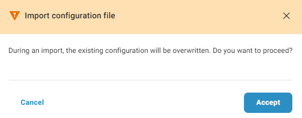
Click Accept.
The file explorer opens.
Navigate to the desired file and click Open.
The BCM configuration is imported.
Configure BTL devices with configurator
The BET supports you in configuring BTL devices. On the CONFIGURATOR tab, you will find the most important setting options and parameters that you need to configure the BTL devices. You can also configure the BTL devices via the PARAMETER tab.
Note
The configurator is only available if a BTL device is physically present.
Configure outputs
You can select one of the two solenoids for each of the two outputs and assign a function to it.
Under Select position encoder, select the solenoid you want to assign to the output. Under Select function, select the function you want to assign to the output:
Position: Measures the current position of the magnet.
Position difference: Measures the difference between two magnets.
Velocity: Measures the change in speed of the magnet.
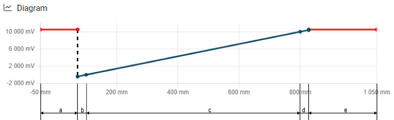
Define measuring range
Within the measuring range specified by the BTL device, you can define the measuring range of the respective output by specifying a zero point and an end point. The characteristic curve of the BTL device is displayed according to your changes:
Area |
Meaning |
|---|---|
a |
Out of measuring range, BTL device switches Error. |
b |
Tolerance range zero point |
c |
Defined measuring range |
d |
Tolerance range End point |
e |
Out of measuring range, BTL device switches Error. |
Enter the zero point under Zero point and the end point of the measuring range under End point. Alternatively, you can use the slider.
The diagram with the current measuring range is updated according to your entries:
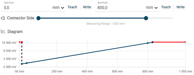
Example: Zero point = 0, end point = 800
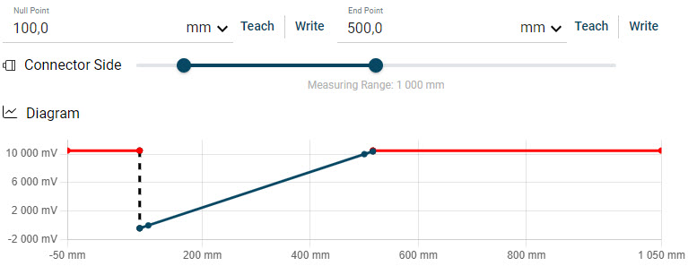
Example: Zero point = 100, end point = 500
To accept a position, click Write. To also write a position directly to the device, click Teach.
Optional: If required, change the unit of the measuring range (X-axis of the characteristic curve). To do this, select the desired unit from the drop-down list:

To change the output voltages of the BTL device corresponding to the measuring points, click More parameters.
The input fields for the output voltages (Y-axis) are displayed:
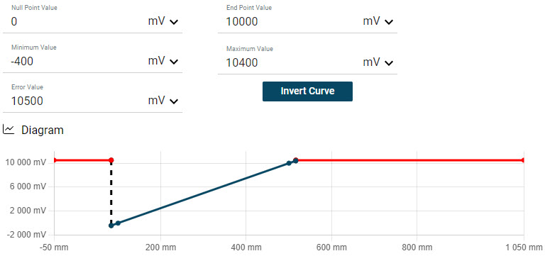
Enter the desired output voltages:
The characteristic curve of the BTL device changes accordingly:
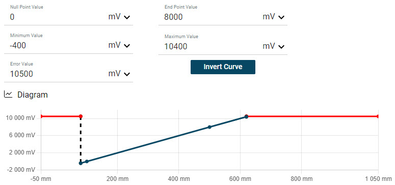
Example: Zero point = 8000 mV
Click Write all parameters to write the changed values to the BTL device.
The values are written to the BTL device according to your input. This completes the configuration.
Reset sensor settings
You have two options for resetting the current values of the BTL device:
You can reset the settings for a technology-specific application to a predefined output value without having to interrupt the connection to the BTL device.
You can reset the values to the factory settings.
To reset the BTL device to the factory settings, click Set factory settings.
To reset the technology-specific application of the BTL device to the predefined values, click Reset application.
Invert sensor characteristic curve
You can swap the zero point value and the end point value and thus invert the characteristic curve.
To invert the sensor characteristic curve, click More parameters and then Invert characteristic curve.
The sensor characteristic curve is inverted.
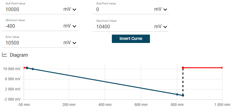
Example: Inverted characteristic curve
Swap parameter values
You can swap the parameter values of output 1 and output 2.
To swap the parameter values, click  and select Swap values.
The parameter values of output 1 and output 2 are swapped.
Copy parameter values
You can copy the parameter values between the outputs.
To copy the parameter values, click and select Copy values from output 1 to output 2 or Copy values from output 2 to output 1.
The parameter values are copied accordingly.