Edit topology
Jul 24, 2026 | 1328 words | 7 min reading time
Delete devices from topology
Click on Planning in the function bar.
Under Balluff projects, click
 .
.
The device is deleted from the topology.
Query and display current device status
The status of the connected devices and the status of the physical topology connection are queried and updated cyclically.
Click Topology in the function bar.
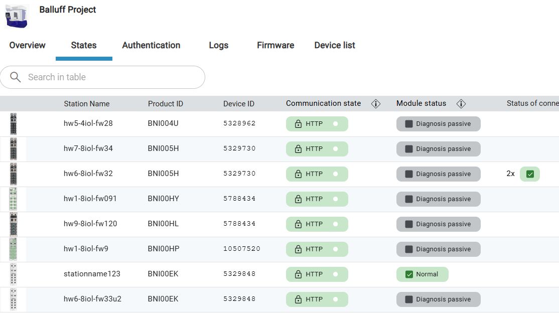
An overview of the network modules of the Balluff project is displayed.
Öffnen Sie die Registerkarte Zustände. Die folgenden Informationen zum aktuellen Verbindungszustand und zum Status der Geräte werden angezeigt:
Show additional information about states
You can display explanatory information on the status of the connections and the status of the connected devices.
Click on
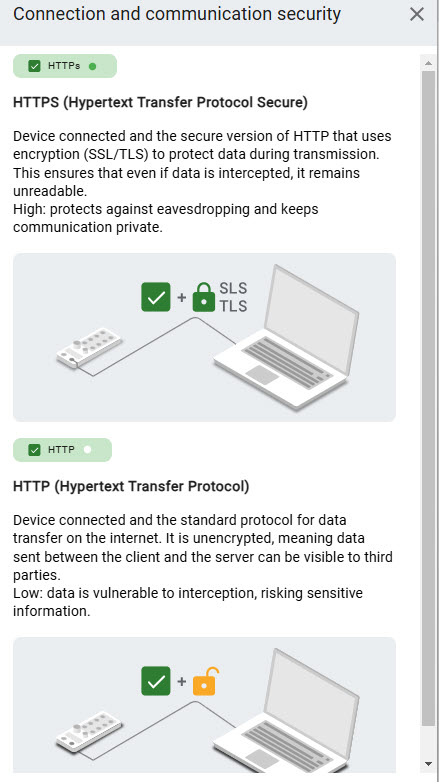
 in the Status of communication column.
Information on the current connection status is displayed:
Click on
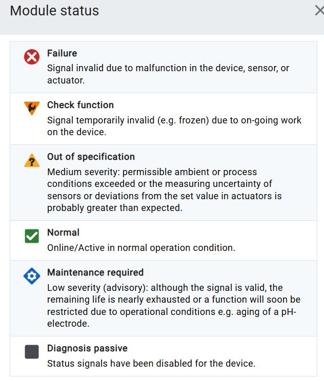
in the Module status column.
An explanation of the various device statuses is displayed:
Manage topology
To manage topologies and the IO-Link network modules and devices used in them, you can display and export a list of all devices.
Display and export device list of all devices
You can display a list of all IO-Link network modules and IO-Link devices present in the current topology. The list facilitates the documentation of the IO-Link topology installed in the machine / plant by allowing you to save it as a CSV file - compatible with Excel and many other software products. You can also export the list as a parts list for the Balluff webshop, making it easier to request and order devices.
Click Topology in the function bar.
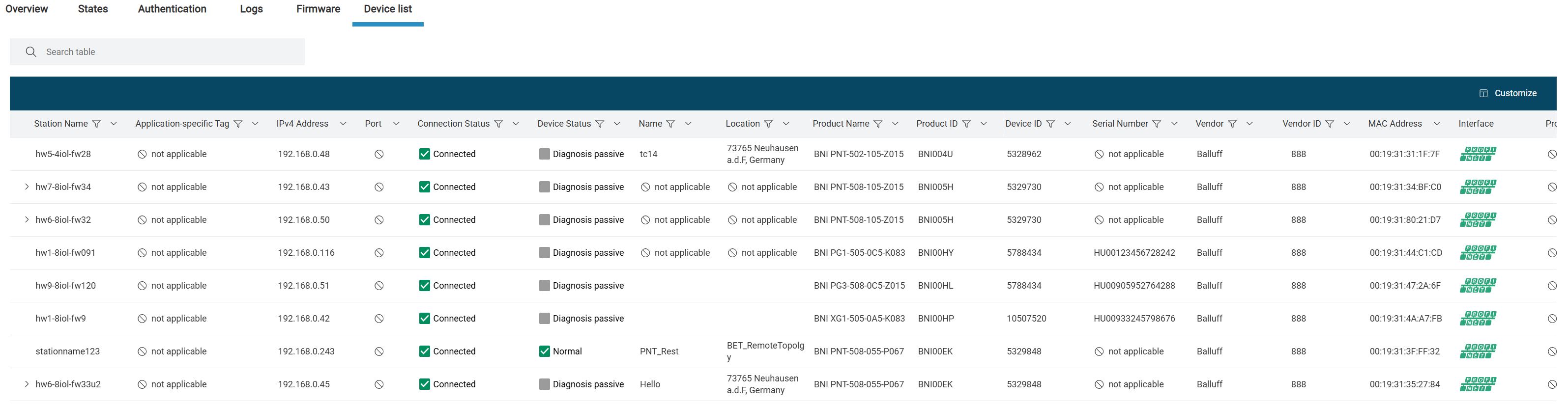
Open the Device list tab.
The device list is displayed.
To export the device list, click EXPORT.
The following menu appears:
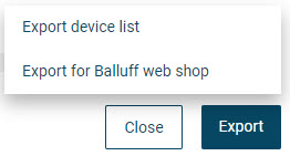
You have the following options:
EXPORT DEVICE LIST: Select this option to export the entire device list.
EXPORT DEVICE LIST FOR BALLUFF SHOPPING CART: Select this option to export the device list for further processing in the Balluff webshop, see FAQ about importing the device list into the Balluff shopping cart.
An export file in *.CSV format will be created, which you can save in the file system.
Show topology overview
The topology overview provides you with a quick overview of the IO-Link network modules available in the currently loaded topology and their connected devices, including connection and device status.
For further editing of an IO-Link network module or device, you can switch directly to its detailed view.
Show device information
Click Topology in the function bar.
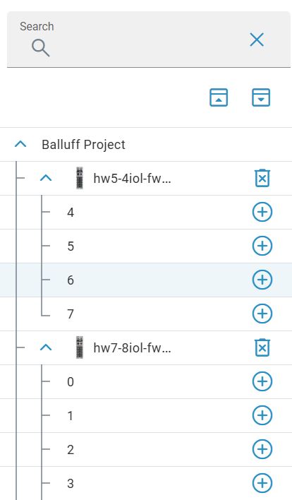
The Balluff project is displayed. The table shows the IO-Link network modules currently present in the topology with the most important information.
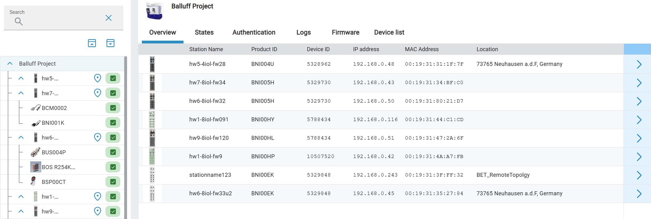
To call up the details of a network module, click
 or click on the network module under Balluff projects.
To call up the details of a device, click on the device under Balluff projects.
For more information, see View and edit device details.
Import IODDs and IOLMs
You can import devices from the catalog in Planning. However, you can also directly import the device description files (IODDs and IOLMs) of a device that are saved locally:
Click on Planning in the function bar.
The following dialog appears:
Click on
 next to a free port.
In the sidebar that now opens, click
 next to the search field.
The following dialog appears:
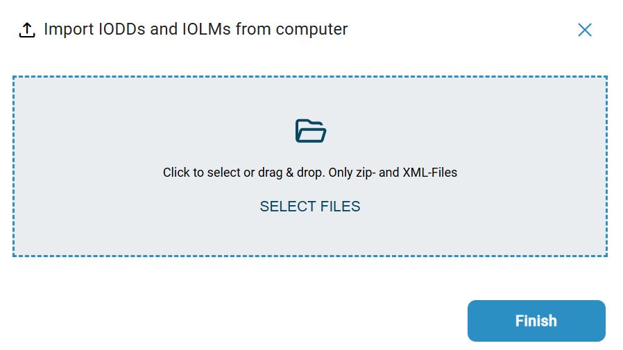
Drag the desired device description file within the dashed frame with the left mouse button pressed and release the mouse button to upload it. Alternatively, you can click inside the frame area to select the file in the file system.
The device description file is imported.
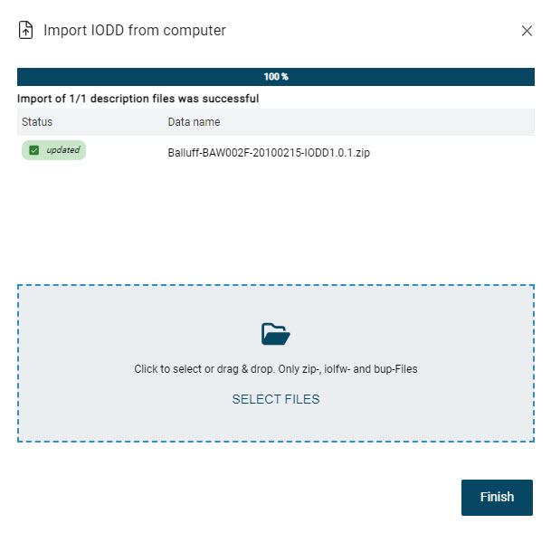
Click Close.
The device description file is added or updated.
Import topology
You can import a previously created topology saved in ZIP format back into the BET . The import includes the port settings of the IO-Link network modules and the device parameters of the connected IO-Link devices.
In addition, you can select whether the device parameters are to be written to the physical devices during import.
Note
There are restrictions on what data can be imported.
Selection of the file to import and import
Click
 in the function bar and then
  .
.
If you have a topology open in the main view, a dialog opens where you choose whether or not to apply the changes to the current topology. You have the following options:
CANCEL: Closes the dialog. You return to the current topology.
SAVE: Closes the current topology and allows you to save the changes before importing, see Save topology.
DO NOT SAVE: Closes the current topology without saving the changes and opens a dialog to import the topology.
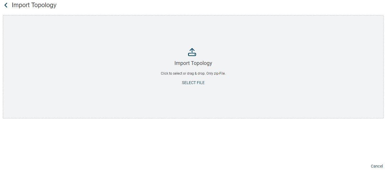
Drag the desired topology file within the area with the left mouse button pressed and release the mouse button to upload the topology. Alternatively, you can click inside the area to select the file in the file system.
A dialog appears showing the IO-Link network modules and IO-Link devices to be imported:
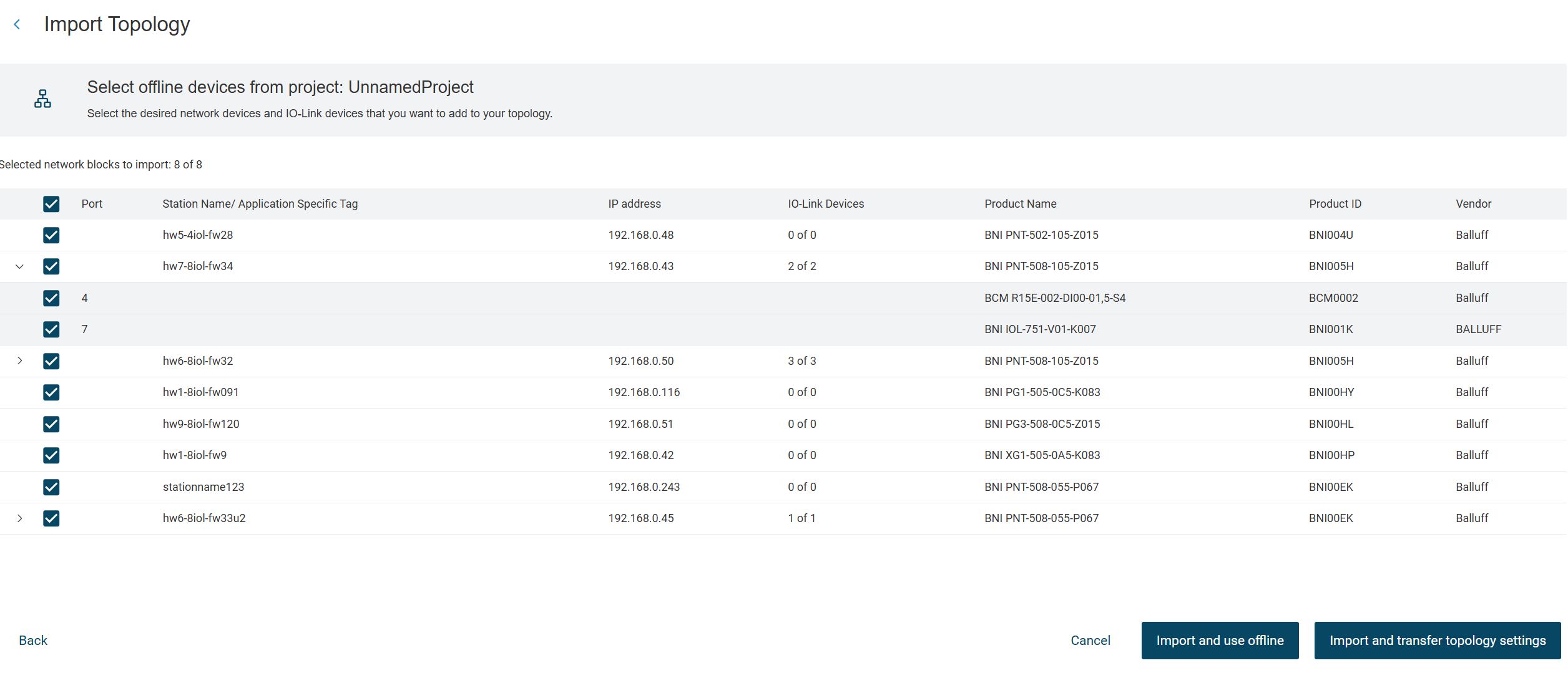
You have the following options:
IMPORT AND USE OFFLINE: Imports the selected IO-Link network modules and IO-Link devices into the configured topology, see Import topology and use offline.
IMPORT AND TRANSFER TOPOLOGY SETTINGS: Imports the selected IO-Link network modules and IO-Link devices into the configured topology and writes the settings to the physical devices in the field, if available, see Import topology and use online.
Import topology and use offline
Select the IO-Link network modules and IO-Link devices that you want to import.
Click IMPORT AND USE OFFLINE.
The selected IO-Link network modules and IO-Link devices are loaded in the main view.
Import topology and use online
Select the IO-Link network modules and IO-Link devices that you want to import.
Click IMPORT AND TRANSFER TOPOLOGY SETTINGS.
For the imported topology, a corresponding topology is searched for in the field and the matching is displayed in a dialog:
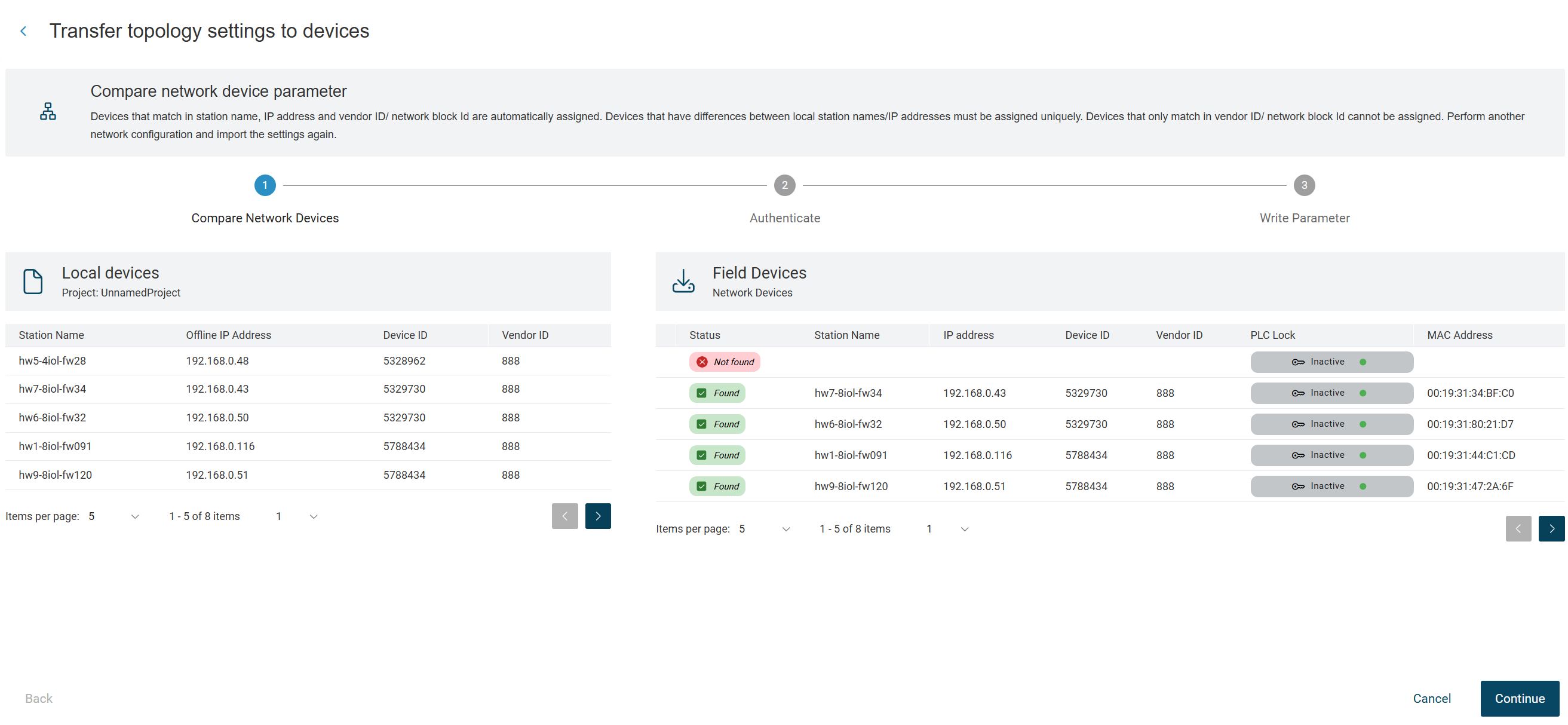
If the topology you want to import matches the topology in the field, click NEXT.
The following warning message appears:
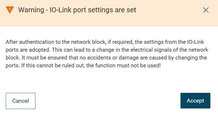
Read the notice carefully and click Accept.
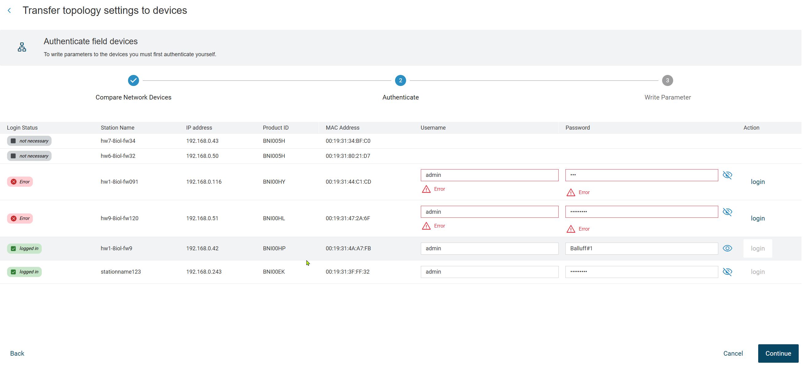
If, necessary, authenticate to the IO-Link network modules and click NEXT.
The following warning messages appear:
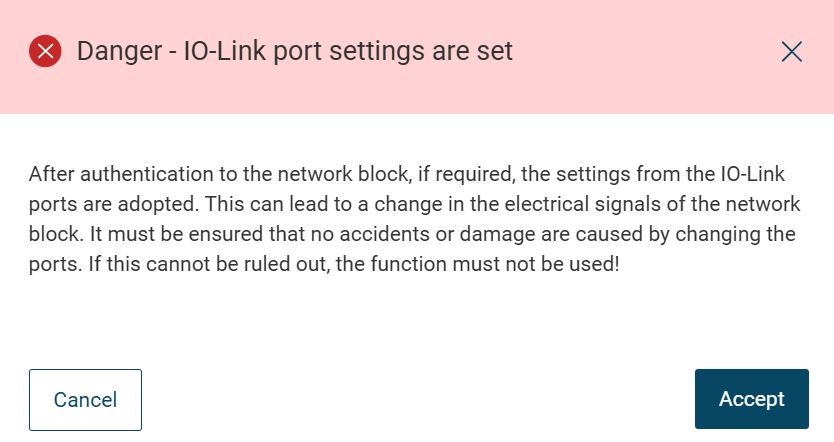
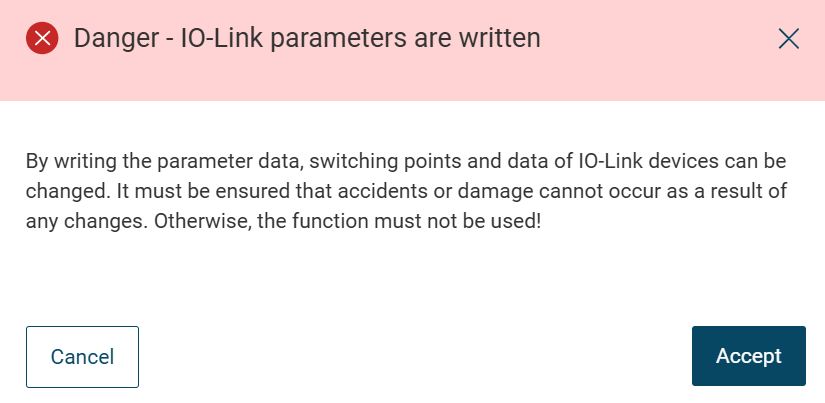
Read the instructions carefully and click ACCEPT.
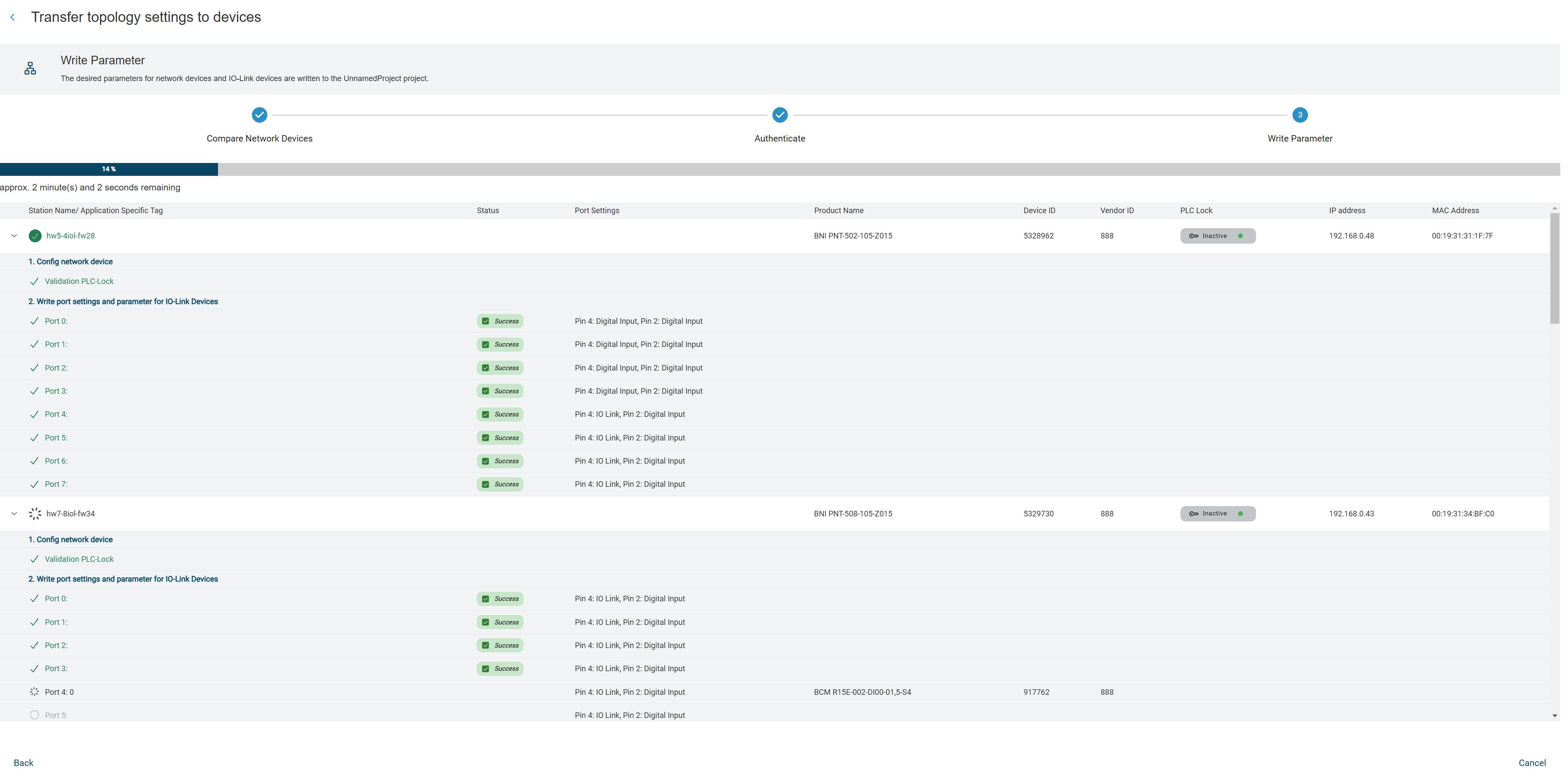
The device parameters from the topology are written to the devices in the field.
If the imported parameters have differences with the current read-only parameters, the following window will be displayed:
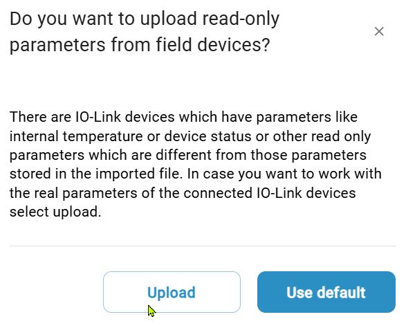
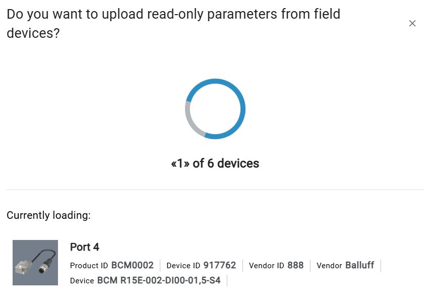
Here you have the option of loading the current, read-only parameters into the topology by clicking on Upload. To do this, click on Upload. The parameters are read from the devices and written to the topology.
Once the topology settings have been applied to the devices, you will see the result of the import:
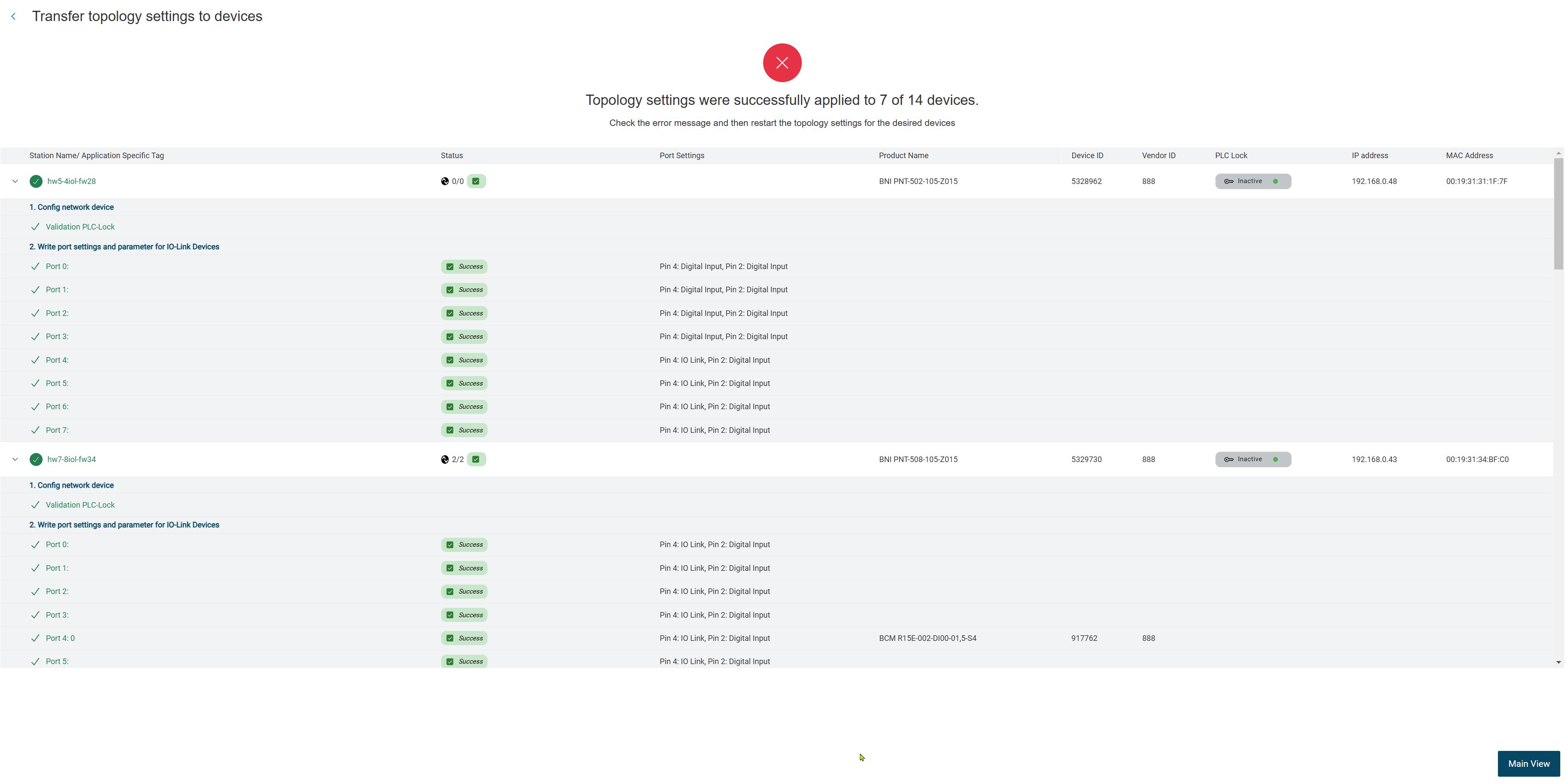
Click MINAL VIEW to load the imported topology in the main view.
Restore topology
When you log out of BET , an internal backup of the current topology is automatically created with all devices and settings. When restarting, BET checks whether a backup is available. After logging in, a message is displayed if this is the case. The notification provides information about the backups, such as the topology name and date, and enables the topologies to be restored at the time of logging out.
Log in to BET , see Log in as a user.
If there are backups of topologies, the following notification appears:
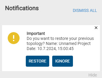
Click REPEAT.
The topology is restored.
If you want to delete the backups, click IGNORIZE.
The backup will be deleted.
Save topology
You can save the current topology including the port settings of the IO-Link network modules and parameters of the IO-Link devices. You can then import the saved ZIP file back into BET at any time, see Import topology. If you save a topology, you have the following options for dealing with parameters that have been changed but not yet written to the physical device.
Click
in the function bar and then  .
.
If you have opened a topology in the main view, a dialog opens in which you can choose whether you want to save the topology with the current changes or discard the changed parameters.
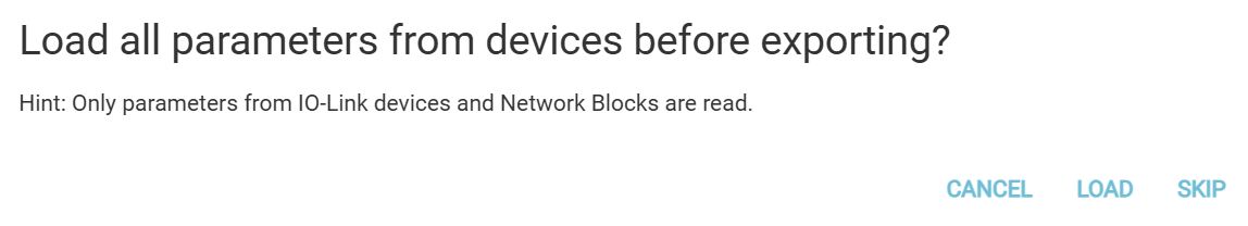
CANCEL: Closes the dialog. You return to the current topology.
*Load: The parameters of all IO-Link devices and the port settings of the IO-Link network modules are read from the physical devices and written to the file. Depending on the size of the topology, loading can take a long time.
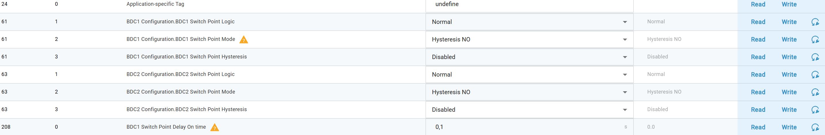
Parameters changed in the topology are not saved in the topology file.
Example: Display of changed but not written parameters in topology before saving:
Note
Process data of the devices and all other settings of the IO-Link network modules cannot be read out and saved.
Skip: Closes the current topology and allows you to save the changes, see.
Before saving, the changed parameters are overwritten with the current values of the physical devices.
Note
Discarded or reset parameter data cannot be restored.
Warning
DANGER OF ACCIDENT! By changing parameter data, switching points and data of IO-Link devices can be changed. Before resetting/writing the changes, ensure that the change cannot cause accidents or damage. The function must not be used if accidents/damage can occur as a result of reading/writing process data.
Select the desired option.
You will be prompted to save the file to the file system.
Choose a location, assign a file name, and click Save.
Note
Make sure that the topology file is saved with the .ZIP file extension.
The topology is saved according to your settings.