Installation and connection
Installation
Note
For dimensions, see Mechanical dimensions of the product
Note
You can find mounting accessories under www.balluff.com on the product page.
► Fasten the module with 2 M6 screws and a tightening torque of 3 Nm using the mounting holes (see Device overview).
Requirements for complying with the protection classes: For IP67, all plugs and caps must be properly connected and the tightening torque of 0.6 Nm must be observed (see data sheets of connectors and caps).
Electrical connection
Power supply
Notice
Unwanted voltage dips
Non-separated electric circuits of the power supplies for sensor and actuator can lead to unwanted voltage dips of the sensor supply when switching actuators.
► Fuse the power supplies for sensors and actuators separately.
► Make sure that the power supply of the device is sufficiently dimensioned to cover start-up and peak currents and design the fuse protection concept accordingly.
Notice
Overcurrent
Defective or missing fuses in the power supply for sensor and actuator will damage them.
► Use a fuse or intelligent power supply (current monitoring designed for max. 4 A for BNI LH1-…-_012).
► Connect the protective earth conductor to the FE terminal.
► Connect the incoming IO-Link line to the sensor hub.
Notice
Loss of function and property damage
Improper installation, e.g. due to misconnection or incorrect polarity of the connections, can result in a loss of the function and property damage.
► Take measures to prevent misconnection or polarity reversal.
► Prevent tampering at the connections.
► Never exceed the value of 36 V between any of the pins.
Note
If possible, supply power to the sensor/module and actuator using an independent power source to ensure independent operation in the event of a power failure.
Note
For UL: observe cable requirements and power supply requirements (see section xxxxxxx).
The supply voltage for the module is provided via the IO-Link interface from the higher-level IO-Link master.
There are two different supply voltages: US1, and UA:
– US1 supplies the module and also the connected sensors (Pin 1 of the analog input ports).
– UA is the supply of the analog outputs (Pin 1 of the analog output ports).
IO-Link interface (XF1)
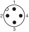
PIN |
Function |
|---|---|
1 |
US1 - Supply voltage for the module and connected sensors |
2 |
UA - Supply voltage for actuators |
3 |
GND, reference potential |
4 |
C/Q, IO-Link data transmission channel |
Analog output ports (X01…X04)
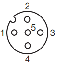
PIN |
Function |
|---|---|
1 |
UA - Supply voltage for the connected actuator |
2 |
Analog output signal (current or voltage) to control the connected actuator |
3 |
GND, reference potential |
4 |
Not connected |
5 |
Function earth |
Output signal range
The analog output ports are freely configurable and can be set independently for the output of a voltage or current signal with the following values:
Analog output signal |
Nominal range |
|---|---|
Voltage |
0…10V |
Voltage |
5…10V |
Voltage |
-10…+10V |
Voltage |
0…5V |
Voltage |
-5…+5V |
Voltage |
1…+5V |
Current |
4…20mA |
Current |
0…20mA |
One actuator can be connected to each of the analog output ports. The module supplies the connected actuator with +24 V (Ua actuator voltage). The product supports single-ended mode (asymmetrical), the output signal is provided between pin 2 and pin 3.
Analog input ports (X05…X08)
PIN |
Function |
|---|---|
1 |
US - Supply voltage for the connected sensors |
2 |
Analog input signal 1 (current or voltage) |
3 |
GND, reference potential |
4 |
Analog input signal 2 (current or voltage) |
5 |
Function earth |
Input signal range
The analog input ports are freely configurable and can be set independently for the input of a voltage or current signal with the following values:
Analog input signal |
Nominal range |
|---|---|
Voltage |
0…10V |
Voltage |
5…10V |
Voltage |
-10…+10V |
Voltage |
0…5V |
Voltage |
-5…+5V |
Voltage |
1…+5V |
Current |
4…20mA |
Current |
0…20mA |
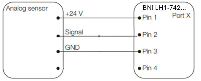
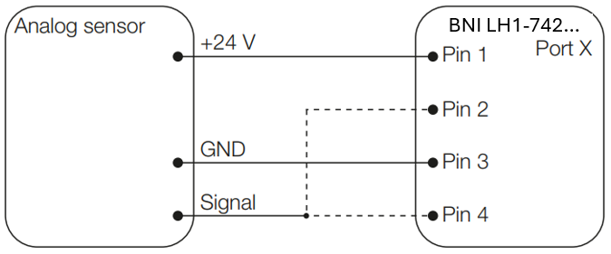
One sensor can be connected to each of the analog ports. The module supplies the connected sensors with +24 V (Us sensor voltage). Different sensor types can be connected using different wiring techniques.
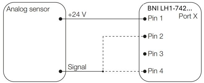
Connection concept of 2-wire technology
2-wire current sensors (4…20 mA) have the sensor supply and signal lines in common. The output of the sensor can be connected either to Pin 2 or to Pin 4 depending on the configuration.
Note
Only current sensors can be connected with the 2-wire technology.
Connection concept of 3-wire technology
The product supports single-ended mode (asymmetrical), the signal must be applied between pin 2/pin 4 and pin 3. This mode can be used for 3-wire sensors.
Grounding
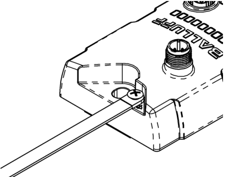
To counteract EMC interference, the functional earth connection must be used.
► Connect the earth terminal to the functional earth (FE) of the machine.
Note
The FE connection between the housing and the machine must have a low impedance and be as short as possible.
► Use the grounding strap included in the scope of delivery.
Shielding and cable routing
Shielding
The connection to the higher-level IO-Link master is made with a standard sensor cable. Analog sensors and actuators are connected to the described hubs using standardized, shielded cables.
Note
Since the housings are made of non-conductive material, interfering signals cannot just flow through the shielding to the FE. The shielding of the cable should be connected to the FE (functional earth) either on the sensor/actuator or module side. If connection is not possible on the sensor/actuator side, the adapter cable available from Balluff as an optional accessory can be used. The adapter cable routes the shielding of the cable to in 5 of the port and thus to FE.
Cable length
The IO-Link connection cable may be max. 20 meters long, the connection cables between analog sensors, digital sensors as well as actuators and hub max. 30 meters.