Product description
In this section, you will find detailed information about the product, including its construction, function, display elements, and labeling.
Construction
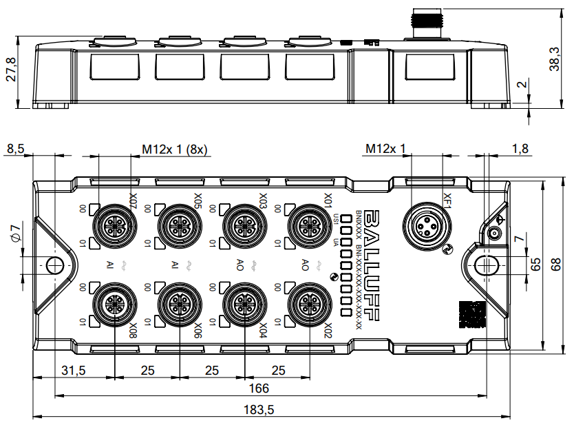
The following picture gives an overview of the products most important dimensions.
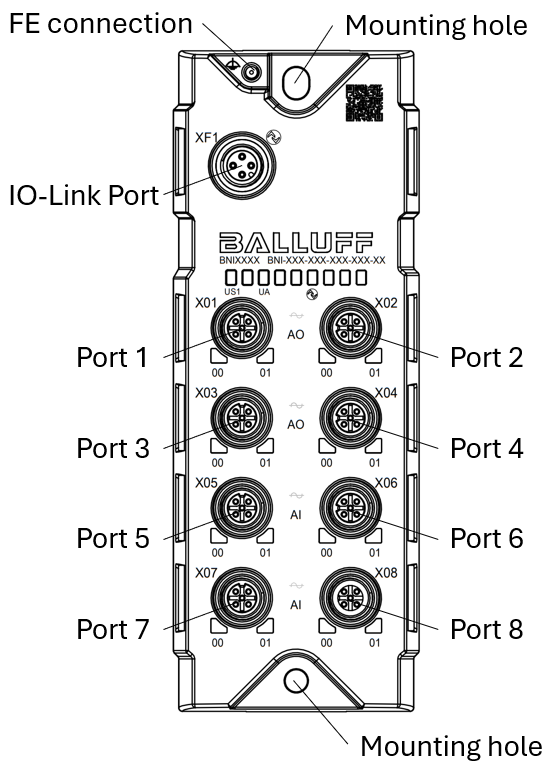
The connections of the device are designated as the next picture defines.
Function
The product feature four freely configurable analog input and four freely configurable analog output ports. The connection to the higher-level master module is made via the IO-Link protocol. Functionally, the hub module is comparable to a passive distribution box: Recording of digital signals and forwarding via the IO-Link interface or forwarding of the control signals coming via IO-Link to connected actuators.
Note
For configuration information, see configuration guide at www.balluff.com on the product page.
Port |
Function |
|---|---|
Port 1 |
Analog output (current or voltage) |
Port 2 |
|
Port 3 |
|
Port 4 |
|
Port 5 |
Analog input (current or voltage) |
Port 6 |
|
Port 7 |
|
Port 8 |
Display Elements
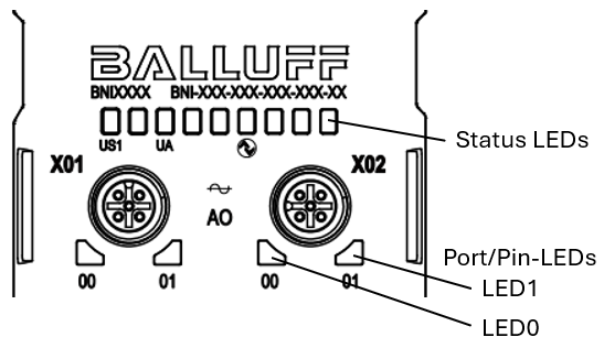
Module status LEDs
The module status LEDs provide information about the operating voltage and the communication status of the device. The following table gives an overview of the different LED states and their meaning.
For more information, see Module status LEDs.
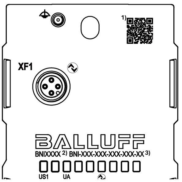
Labeling
Position |
Description |
|---|---|
1 |
QR code (link to the download area on the product page) |
2 |
Order code |
3 |
Type |
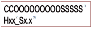
Position |
Description |
|---|---|
1 |
Serial number |
2 |
Hardware version |
3 |
Software version |
Type code
1 |
2 |
3 |
4 |
5 |
|
|---|---|---|---|---|---|
BNI |
LH1 |
742 |
S13 |
R012 |
|
Position 1: Product Family
BNI = Balluff Network Interface
Position 2: Product Line
L = IO-Link
H = Hub
1 = Entry Line
Position 3: Function
742 = 4 analog output (V/A) and 4 analog input (V/A)
Position 4: Variant
S13 = single-channel monitoring, IO-Link 1.1.4
Position 5: Mechanical version
P012 = Plastic housing without auxiliary power supply connector