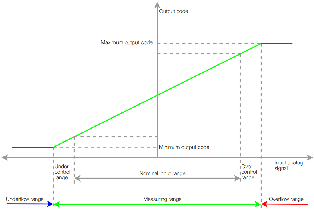
With the function Configuration of analog ports, the analog ports can be configured independently of each other. Each input port can function either as a voltage input or as a current input. The analog signal can be connected to either Pin 2 or Pin 4.
The analog outputs can functions as a voltage output or as a current output. The analog signal is provided always on Pin 2.
Configuration of analog ports - Input signal range
Analog input signal
Nominal range
Voltage
0…10 V
Voltage
5…10 V
Voltage
−10…+10 V
Voltage
0…5 V
Voltage
−5…+5 V
Voltage
1…+5 V
Current
4…20 mA
Current
0…20 mA
The modules support many standard input signal ranges see Configuration of analog ports - Input signal range. In some cases, an analog sensor has a higher linear output range than the nominal output range. For example, a sensor with an output of 0…10 V can generate a voltage between −0.5 V and 10.5 V. It outputs errors at a signal of < 0.5 V or > 10.5 V.
Nominal and measuring range
The selected nominal range is determined by the type of the connected sensor (e.g.: 0…10 V or 4…20 mA). For each configured nominal range, the module has under- control and over-control ranges, in which the sensors often issue error messages (signal value outside the nominal range).
The nominal range together with the under-control and over-control range forms the measuring range. The module supplies digitalized values in the measuring range.
Configuration of analog ports - Nominal and measuring range
Nominal range
Measuring range input
Signal range output
Input value min.
Input value max.
Output value min.
Output value max.
0…+10V
-1.759V
+11.759V
0V
10V
+5…+10V
+4.12V
+11.759V
+5V
+10V
-10…+10V
-11.759V
+11.759V
-10V
+10V
0…+5V
-0.879V
+5.879V
0V
+5V
-5…+5V
-5.759V
+5.879V
-5V
+5V
+1…+5V
0.121V
+5.879V
+1V
+5V
4…20mA
2mA
22mA
4mA
20mA
0…20mA
0mA
22mA
0mA
20mA
Configuration of analog ports - Nominal and measuring range
Overflow/underflow range
In the overflow and underflow range, no AD conversion takes place; there the module supplies the maximum or minimum value as Digitalized Input Value Port X, and sets the associated status bits (underflow Port X, overflow Port X).
Configuration of analog ports - Overflow/underflow range
Nominal range
Underflow range
Overflow range
0…10 V
< −1.759 V
> +11.759 V
5…10 V
< +4.12 V
> +11.759 V
−10…+10 V
< −11.759 V
> +11.759 V
0…5 V
< −0.879 V
> +5.879 V
−5…+5 V
< −5.879 V
> +5.879 V
1…+5 V
< 0,121 V
> +5.879 V
4…20 mA
< 2 mA
> 22 mA
0…20 mA
–
> 22 mA
Note
The module cannot measure negative currents. There is no underflow range for the input range 0…+20 mA.
Configuration of analog ports – Process Data for Underflow/Overflow Port 5-8
Bit 7
Bit 6
Bit 5
Bit 4
Bit 3
Bit 2
Bit 1
Bit 0
Underflow Port 8
Underflow Port 7
Underflow Port 6
Underflow Port 5
Overflow Port 8
Overflow Port 7
Overflow Port 6
Overflow Port 5
Configuration of analog ports – Process Data for Underflow/Overflow Port 5-8, values
Value
Meaning
0
Input signal not in underflow range (Bit 4…7) or in overflow range (Bit 0…3)
1
Input signal in underflow range (Bit 4…7) or in overflow range (Bit 0…3)
ISDU
Configuration of analog ports – ISDU
Name
Index
Subindex
Access
Length
Data Type
Data Storage
Default
Analog Mode
0xF0 (240)
0
R/W
8 Byte
Yes
Analog Mode Port x
1…8
R/W
1 Byte
UINT8
No
0xFF
Analog Port Pin Assignment
0xF2 (242)
0
R/W
4 Byte
Yes
Analog Port Pin Assignment Port x
1…4
R/W
1 Byte
UINT8
No
0x01
Safe States
0xFA (250)
0
R/W
4 Byte
Yes
Safe states Port x
1…4
R/W
1 Byte
UINT8
No
0x03
Note
During the writing of the ISDUs, the AD conversion is stopped for a short time.
Analog Mode
The Analog Mode parameter sets the type and range of the analog signal for each port. The subindex determines which port will be read/set.
Configuration of analog ports – Analog Mode
Subindex
Meaning
1
Analog Mode Port 1
2
Analog Mode Port 2
3
Analog Mode Port 3
4
Analog Mode Port 4
5
Analog Mode Port 5
6
Analog Mode Port 6
7
Analog Mode Port 7
8
Analog Mode Port 8
The following values can be set:
Configuration of analog ports – Analog Mode, Settings
Value
Port Function
0x00
0 V…+10 V
0x01
4 mA…20 mA
0x02
+5 V…+10 V
0x03
-10 V…+10 V
0x04
0 V…+5 V
0x05
0 mA…20 mA
0x06
-5 V…+5 V
0x07
1V…5V
0xFF
Port is switched off
The default value for all ports is: 0xFF, the ports are switched off.
Analog Port Pin Assignment
The Analog Port Pin Assignment parameter is used to assign the analog port signal to the pin.
Configuration of analog ports – Analog Port Pin Assignment
Subindex
Meaning
1
Pin Assignment Port 5
2
Pin Assignment Port 6
3
Pin Assignment Port 7
4
Pin Assignment Port 8
The following values can be set:
Configuration of analog ports – Analog Port Pin Assignment, Settings
Value
Mode
0x00 (0)
Single-ended mode at Pin 2. Signal at Pin 2 (referenced to Pin 3)
0x01 (1)
Single-ended mode at Pin 4. Signal at Pin 4 (referenced to Pin 3)
The default value for all analog input ports is: 0x01, Single-ended mode at Pin 4. Signal at Pin 2 (referenced to Pin 3).
Note
The analog outputs are always provided on Pin 2, therefore no additional setting are available for those ports.
Safe States
In the Safe States Register the applied analog output signal can be defined for the case when the IO-Link Master sets the PDO (Process Data Output Valid) flag to invalid or if the IO-Link communication gets aborted.
Configuration of analog ports – Safe state
Subindex
Meaning
1
Safe state Port 1
2
Safe state Port 2
3
Safe state Port 3
4
Safe state Port 4
The following values can be set:
Configuration of analog ports – Safe state values
Value
Safe state
0x00 (0)
Output will be set to minimal value according to the selected output signal range
0x01 (1)
Output will be set to the middle value according to the selected output signal range
0x02 (2)
Output will be set to maximal value according to the selected output signal range
0x03 (3)
The last valid output value will be kept
The default value for all ports is: 0x03, the last valid output value will be kept.
System Commands
Configuration of analog inputs – System Commands
Command Value
Device Action
0x81 (129)
Application Reset – Resets writable parameters to the default value.
0x82 (130)
Reset Factory Settings – Resets writable parameters to the default value.
Events
Configuration of analog inputs – Events
Event Code
Event Type
Description
Device Status
0x8CA1 (36001)
Warning
Analog Input Value Overflow – The analog input value is too high
0 – Device is operating properly
0x8CA2 (36002)
Warning
Analog Input Value Underflow – The analog input value is too low
0 – Device is operating properly
There is an event code for underflow and as well as for overflow, independent of the port at which the events occurred. The exact source of the event can be taken from the process data.
If an event (for example, overflow) is active on one port (e.g. Port 0) and another port (e.g. Port 4) also reaches the overflow range, no new event is generated (because an event has already been sent and is active). The event disappears when all ports (in the example: Port 0 and Port 4) have left the overflow range.