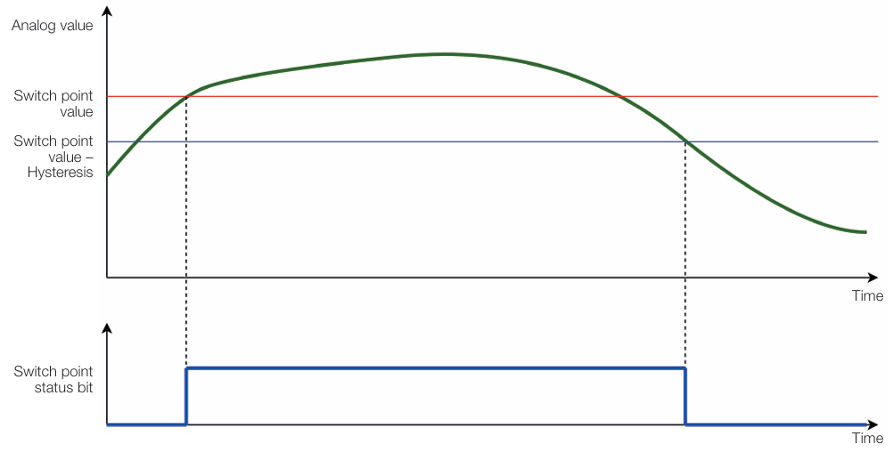
The switch point function offers the possibility to compare the digitalized analog value with a predefined limit value (switch point value) to generate a status bit in the process data.
Each analog input port can have two switch points. If the input signal is greater than the switch point, the associated status bit is set. If the input signal falls below the switch point again, the status bit is reset. To avoid flickering of the status bit, the status bit is set with a hysteresis.
Switch point function with hysteresis
Process Data
Switch point – Process Data
Name
Description
Direction
Analog Port Switch Point 1 Port 5 – Port 8
Switch point 1 values for 4 analog ports
Input
Analog Port Switch Point 2 Port 5 – Port 8
Switch point 2 values for 4 analog ports
Input
Process data bits for analog port switch point 1 PD Object
Switch Point - Analog Port Switch Point 1 PD Object
Bit 7
Bit 6
Bit 5
Bit 4
Bit 3
Bit 2
Bit 1
Bit 0
Switch Point 1 Port 8
Switch Point 1 Port 7
Switch Point 1 Port 6
Switch Point 1 Port 5
Reserved
Reserved
Reserved
Reserved
Switch Point - Analog Port Switch Point 1 PD Object, values
Value
Meaning
0
Limit value for switch point 1 is not reached at port. Switch point inactive.
1
Limit value for switch point 1 is reached at port. Switch point active.
Process data bits for analog port switch point 2 PD Object
Switch Point - Analog Port Switch Point 2 PD Object
Bit 7
Bit 6
Bit 5
Bit 4
Bit 3
Bit 2
Bit 1
Bit 0
Switch Point 1 Port 8
Switch Point 1 Port 7
Switch Point 1 Port 6
Switch Point 1 Port 5
Reserved
Reserved
Reserved
Reserved
Switch Point - Analog Port Switch Point 2 PD Object, values
Value
Meaning
0
Limit value for switch point 2 is not reached at port. Switch point inactive.
1
Limit value for switch point 2 is reached at port. Switch point active.
ISDU
Switch Point – ISDU
Name
Index
Subindex
Access
Length
Data Type
Data Storage
Default
Switch point 1
0xF6 (246)
0
R/W
8 Byte
Yes
Switch Point 1 Port x
1…4
R/W
2 Byte
INT16
No
0x0000
Switch point 2
0xF7 (247)
0
R/W
8 Byte
Yes
Switch Point 2 Port x
1…4
R/W
2 Byte
INT16
No
0x0000
Switch Point Enable
0xF8 (248)
0
R/W
1 Byte
Yes
Switch Point Enable Port x
1…8
R/W
1 Bit
BOOL
No
0x00
Switch Point 1, Switch Point 2
The ISDU contains a 16-bit switch point value.
The switch point must always be specified in the process data format that is configured with function Configuration of analog value display (Analog Port Data Format Setting).
Switch point 1, Switch poin 2 – Resolution
Subindex
Meaning
1
Switch point 1 or 2 value for Port 5
2
Switch point 1 or 2 value for Port 6
3
Switch point 1 or 2 value for Port 7
4
Switch point 1 or 2 value for Port 8
The default value for all ports is: 0x0000.
Switch Point Enable
Switch point – Switch Point Enable
Subindex
Meaning
1
Activate switch point 1 for Port 5
2
Activate switch point 1 for Port 6
3
Activate switch point 1 for Port 7
4
Activate switch point 1 for Port 8
5
Activate switch point 2 for Port 5
6
Activate switch point 2 for Port 6
7
Activate switch point 2 for Port 7
8
Activate switch point 2 for Port 8
The following values can be set:
Switch point – Switch Point Enable, values
Value
Meaning
0x00 (0)
Switch point deactivated
0x01 (1)
Switch point activated
The default value for all ports is: 0x00,the switch points are deactivated.
System Commands
Switch point – System Commands
Command Value
Device Action
0x81 (129)
Application Reset – Resets writable parameters to the default value.
0x82 (130)
Reset Factory Settings – Resets writable parameters to the default value.