Initial Modbus/TCP device configuration
As an example, the connection of the BNI to a CODESYS control is shown. The exact procedure depends on the project planning software used.
Add the Network Module as Modbus/TCP device
Before you begin
Make sure that:
A new, empty CODESYS project has been created.
The module is connected to the PLC via Ethernet and is powered up.
The module has been assigned a unique IP address.
See: Make network settings.
The module’s bus type has been switched to Modbus/TCP via the WebUI.
See: Change protocol.
Steps
To add the Modbus/TCP device in CODESYS:
Add an Ethernet device.
Right-click the device in the tree and select Add Device… from the context menu.
In the General section of the Ethernet adapter, click Browse… and select the network adapter to use.
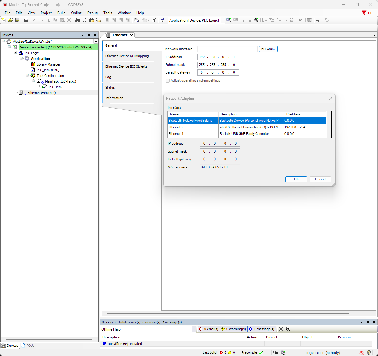
Add a Modbus client.
Below the Ethernet adapter, right-click and select Add Device… from the context menu.
Add a Modbus server.
Below the Ethernet adapter, right-click and select Add Device… from the context menu. The Modbus server represents the network module.
Optional: Rename the device.
Right-click the device in the tree and select Refactoring > Rename from the context menu.
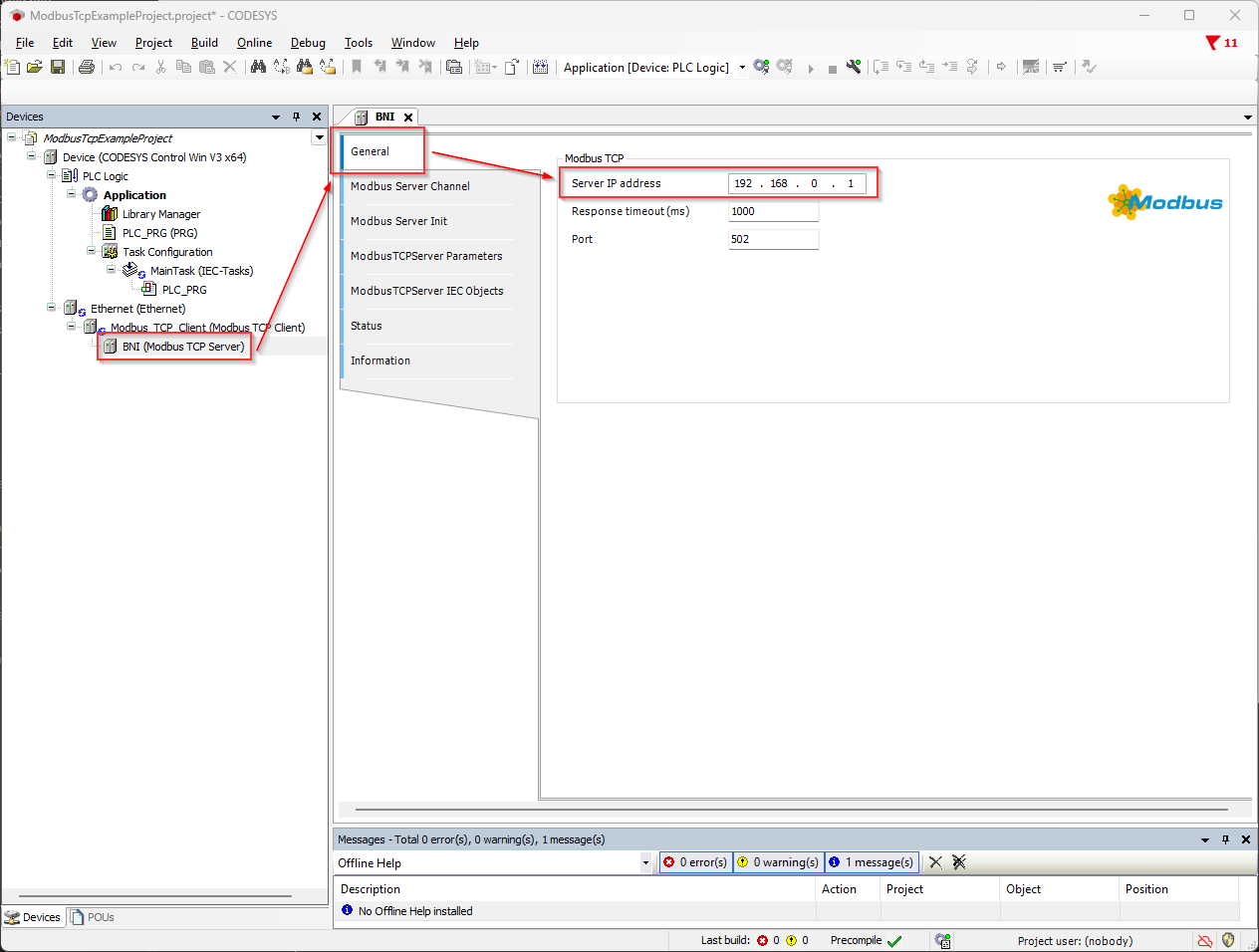
Set the IP address of the network module.
Open the Modbus server device, select General, and enter the IP address of the network module. Make sure that the Port is set to 502 (default).
Download the program to the PLC and start it.
⇒ CODESYS reports an active connection.
Configure ports
Configure the port settings of the network module via the Port Configuration registers, see Registers 9100…9800 – Port Configuration for the register layout.
Note
The port settings can also be configured directly via the WebUI, see I/O ports. However, if the device is replaced, the port modes must then be applied manually again on the new device.
If the port settings are configured in CODESYS instead, they are written to the device automatically every time the PLC program starts.
Set port mode
Configure the port settings (e.g. Pin 2 / Pin 4 port mode) of the network module so that connected IO-Link devices and digital signals are set up as required.
Before you begin
Make sure that:
The Modbus/TCP device has been added successfully. See Add the Network Module as Modbus/TCP device.
Steps
As an example, Port 4 Pin 4 is configured as IO-Link and Pin 2 as Digital Output. Adapt the register offset and value to the desired port and configuration.
To configure the ports in CODESYS:
Select the Modbus server (network module) in the device tree.
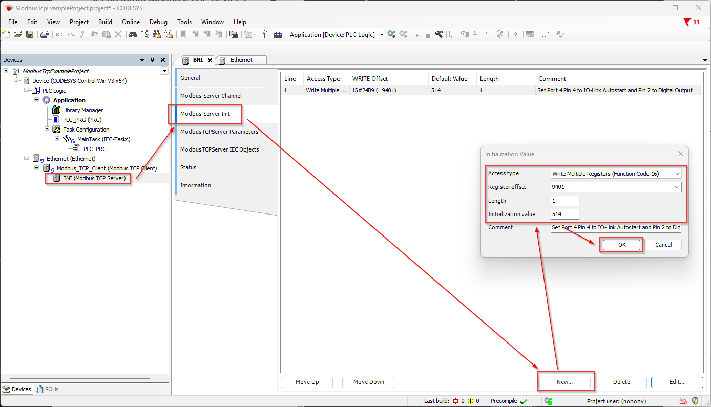
Navigate to Modbus Server Init.
Click New….
In the Initialization Value dialog, select Write Multiple Registers (Function Code 16) as the access type, and enter the register offset and the desired value.
For example, to set port 4 to IO-Link and Pin 2 to Digital Output, use register offset
9401(Port Configuration register for port 4, see Registers 9100…9800 – Port Configuration for the register layout 9100…9800), length1, and initialization value514(hex0x0202).Multiple ascending registers can also be set with an initial value each. For this, set the desired number of registers in the Length field and enter the corresponding initialization value.
Optional: Enter a comment describing the configured value.
Click OK.
Download the program to the PLC and start it.
⇒ The port is set to the configured port mode.
Configure Validation and Backup
Configure the Validation and Backup behavior of an IO-Link port so that the network module checks the connected IO-Link device against the expected Vendor ID and Device ID, and backs up its parameters as required.
Before you begin
Make sure that:
The Modbus/TCP device has been added successfully. See Add the Network Module as Modbus/TCP device.
Pin 4 of the port is configured as IO-Link. See Set port mode.
The Vendor ID and Device ID of the expected IO-Link device are known, e.g. from the device’s datasheet or IODD.
Note
The Vendor ID and Device ID of the currently connected IO-Link device can be read from the IO-Link Port Diagnostic registers
3n01(Vendor ID),3n02and3n03(Device ID), see Registers 3010…3080 – IO-Link Port Diagnostic.
Steps
As an example, Port 4 is configured with Validation and Backup mode Backup + Restore, together with the Vendor ID and Device ID of the expected IO-Link device. Adapt the register offset and values to the desired port and device.
To configure Validation and Backup in CODESYS:
Select the Modbus server (network module) in the device tree.
Navigate to Modbus Server Init.
Click New….
In the Initialization Value dialog, select Write Multiple Registers (Function Code 16) as the access type, and enter the register offset and the desired value.
For example, to set the Vendor ID and Device ID of the expected IO-Link device for port 4, use register offset
9403(Vendor ID) and9404(Device ID MSB, as the low byte of the register value), followed by register offset9405(Device ID LSB) (Port Configuration registers for port 4, see Registers 9100…9800 – Port Configuration for the register layout9100...9800).Multiple ascending registers can also be set with an initial value each. For this, set the desired number of registers in the Length field and enter the corresponding initialization value.
Repeat step 4 to set port 4 to Validation and Backup mode Backup + Restore, using register offset
9402, length1, and initialization value3.Optional: Enter a comment describing the configured value.
Click OK.
Download the program to the PLC and start it.
⇒ The Validation and Backup mode is applied to the configured port, and the connected IO-Link device is checked against the configured Vendor ID and Device ID.
Configure process data channels
Configure cyclic process data channels in CODESYS so that the registers described in Register Description are read and written cyclically and mapped to PLC variables.
Before you begin
Make sure that:
The Modbus/TCP device has been added successfully. See Add the Network Module as Modbus/TCP device.
The relevant ports are configured with the desired port mode. See Set port mode.
Steps
As an example, register 2000 (Digital Input State) is read cyclically and register 2001 (Digital Output State) is configured for writing. Adapt the register offset and access type to the desired registers.
To map the registers in CODESYS:
Select the BNI in the device tree.
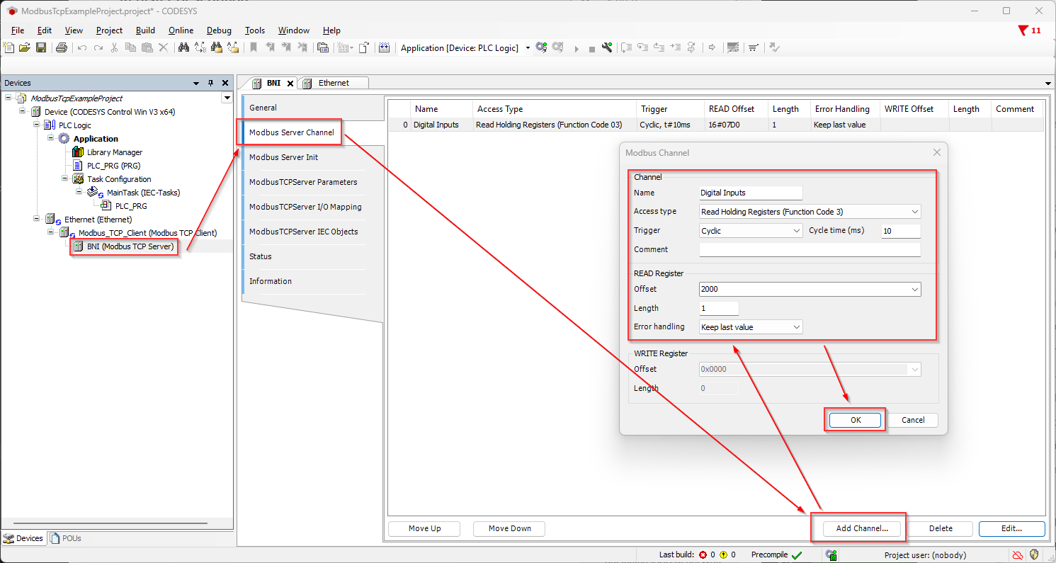
Select Modbus Server Channel.
Click Add Channel….
In the Modbus Server Channel dialog, enter the values for the digital input channel.
For example, to read register
2000(Digital Input State, see Registers 2000, 2001 and 2047, 2048 – Digital Input / Output State for the register layout), enter a name (e.g.Digital Inputs), select Read Holding Registers (Function Code 3) as the access type, select Cyclic as trigger with a valid cycle time, and set the READ Register Offset to2000and Length to1.Click OK.
Navigate to ModbusTCPServer I/O Mapping.
⇒ The added channel is shown here as process data and can be mapped to a PLC variable.
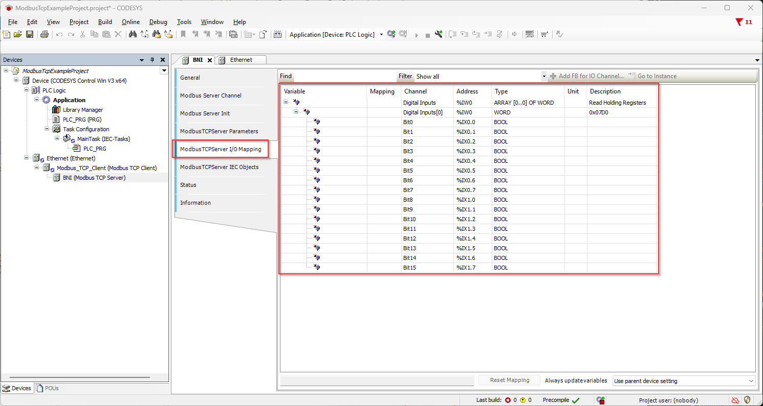
The digital input channel shown as process data in the I/O mapping
Click Add Channel… again to add a channel for the digital output register.
In the Modbus Server Channel dialog, enter the values for the digital output channel.
For example, to write register
2001(Digital Output State), enter a name (e.g.Digital Outputs), select Write Multiple Registers (Function Code 16) as the access type, select Cyclic as trigger with a valid cycle time, and set the WRITE Register Offset to2001and Length to1.Click OK.
⇒ The digital output word is now available in ModbusTCPServer I/O Mapping with the mapped PLC addresses.
Download the program to the PLC and start it.
⇒ The mapped PLC variables cyclically reflect the register values; writing to the output variable sets the corresponding digital output.