Advanced Configuration
Using the IOL_CALL Function Block
To be able to write or read out the ISDU data of connected IO-Link devices during operation, the common programming interfaces of the control manufacturers provide corresponding function modules or libraries.
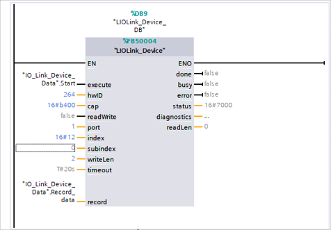
- REQ (execute)
Use Request to start the action in order to write or read data.
- ID (hwID)
The ID is permanently declared by the master via the hardware configuration.
This can be found under System constants in the hardware identification.Select the hardware ID of the module IO-Link_I_O_Ports_1~BALLUFF_8_Port_IO-Link_Master

- CAP Value (cap)
This is assigned by the manufacturer. For Balluff products, it is the value 0xB400.
- Read/Write (read/write)
The command is defined here. To read data, it must be a 0; to write data, it must be a 1.
- Port (port)
Here you select the port to which the device has been connected. The master numbered as 0 and the ports are numbered from 1…8.
- Index (index)
This is the index of the IO-Link subscriber being read out or written. This can be found in the user’s guide for the IO-Link device.
- SubIndex (subindex)
The sub-index is defined by the data to be processed. This can also be found in the operating instructions for the connected IO-Link device.
- LEN (writeLen)
This is the length of the data. This can also be found in the parameter data in the user’s guide for the IO-Link device.
- RECORD_IOL_DATA (record)
A data module is used for communication. The structure must be established in Array of Bytes. The data to be changed is written into this array.
- DONE_VALID (done)
Confirms the successful request to read or write data.
- BUSY (busy)
Shows the working state of the module.
- ERROR (error)
If an error occurs in the function, it is reported here.
- STATUS (status)
Error status of the function
- IOL_STATUS (diagnostics)
Describes the current status or an error.
- RD_LEN (readLen)
Shows how many bytes were read by the module.
The IOL_Call function module composes a telegram that is transferred to the master via acyclic services. The following settings are required for this:
Diagnosis address |
CAP access |
|---|---|
The diagnosis address of module IO-Link_I_O_Ports_1~BALLUFF…_ is used. |
0xB400 |
The telegram set-up is described in the table below.
Read
To be able to read out data, the master must be sent a read task for the corresponding slot/index/subindex.
For this, the telegram must be adapted accordingly (slot, index) and entered at Task 0x03 for reading. The telegram can then be sent to the corresponding module via write command.
The module reads the data from the IO-Link device.
The data can be fetched by reading with the same telegram.
Write
To be able to write data, the network module must be sent a write task for the corresponding slot/index/subindex.
For this, the telegram must be adapted accordingly (slot, index) and entered at Task 0x02 for writing. The telegram can then be sent to the corresponding module via write command.
Integrating Safety-Hub
Note
Please check whether IO-Link is supported by your module before using this function. For more information on product variants that support IO-Link, see Supported product variants.
When project planning for PROFINET devices, a device is mapped as a modular system, which has a headslot and several data modules. The illustrations used here are taken as examples from the Totally Integrated Automation Portal (TIA Portal) project planning software and from the SIMATIC Manager from Siemens AG and are for illustrative purposes only.
The necessary settings depend on the application and are the responsibility of the user. The Safety Hub device (BNI IOF-329-P02-Z038 or BNI IOF-329-P02-Z092) must always be connected via a compatible Balluff network module.
The Safety Hub device is a special case of the IO-Link Devices Submodules: instead of a single submodule, it requires a dedicated slot 1 module variant and a pair of submodules per port (one for secure communication, one for standard communication), as described below.
Placing the Safety Hub Module on Slot 1
The GSDML file provides the data modules available for the respective network module.
Before you begin
Make sure that:
The GSDML file of the PROFINET device has been installed.
Steps
Select module IO-Link I/O ports (w/o IO data) with Safety Hub and ISDU in the hardware catalog and drag and drop it to slot 1.
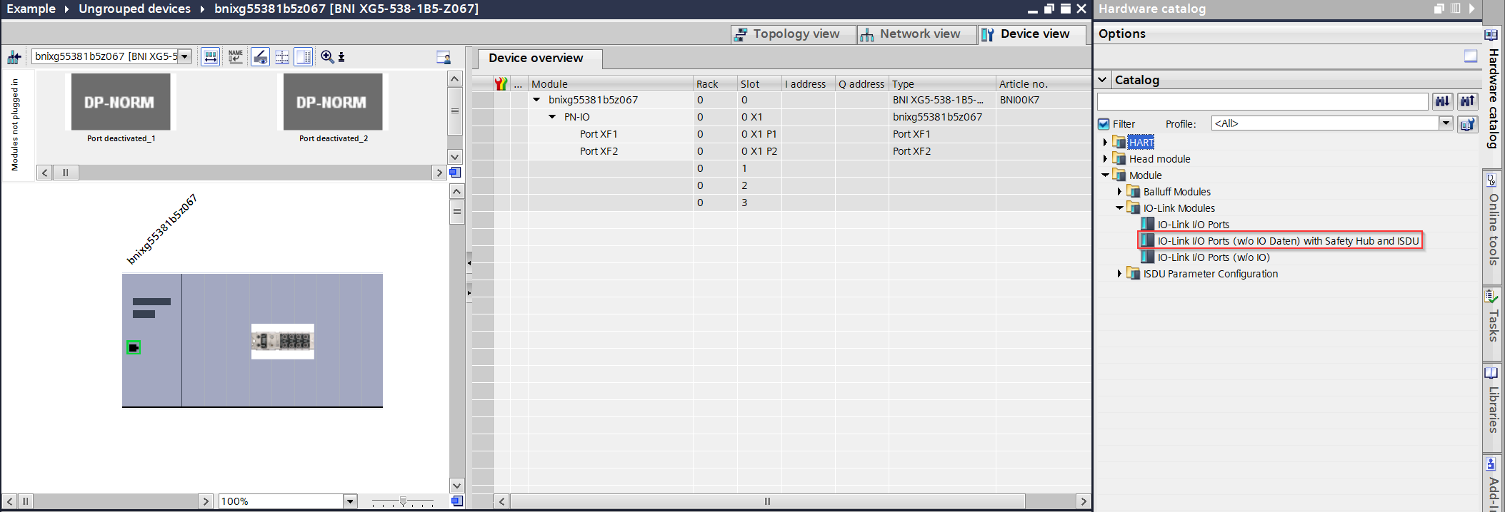
Select module IO-Link I/O ports (w/o IO data) with Safety Hub and ISDU
⇒ The module is placed on slot 1. The list of port subslots is automatically doubled, as the secure IO-Link IO module consists of one sub-module each for secure and standard communication.
Assigning a Safety Hub Device to a Port
The device data for the secure I/O module can be found in the Safety Hub submodule folder of the project planning software.
Before you begin
Make sure that:
The IO-Link I/O Ports (w/o IO data) with Safety Hub and ISDU module has been placed on slot 1.
A Safety Hub device (BNI IOF-329-P02-Z038 or BNI IOF-329-P02-Z092) is connected to the port.
Steps
Delete the default Port deactivated and Empty submodule entries for the port.
⇒ The port’s subslot pair is empty and ready for the new submodules.
From the Safety Hub submodule folder, drag the secure I/O submodule matching the connected device to the upper free slot (1), and drag the Standard I/O submodule to the slot below (2).
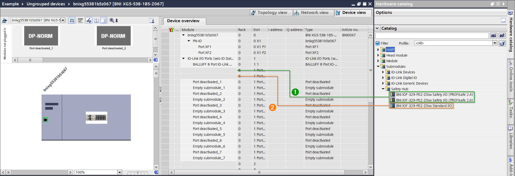
Safety Hub submodules in the hardware catalog: (1) secure I/O submodule to the upper slot, (2) standard I/O submodule to the lower slot
Two secure I/O submodules are available, differentiated by PROFIsafe version: Safety I/O (PROFIsafe 2.4) and Safety I/O (PROFIsafe 2.6).
Note
Which secure I/O submodule to use, and whether a BNI IOF-329-P02-Z038 or BNI IOF-329-P02-Z092 device is required for your application, depends on your safety concept. Consult the Safety Hub product documentation to determine the correct variant.
⇒ The secure and standard I/O submodules appear in the device overview under the port’s subslots.
Note
For further configurations, see the Safety Hub guide.
Note
After integrating and configuring the module, the master must be restarted!
Ring Topology
The network module also supports the ring topology with media redundancy, which is enabled via the Media Redundancy Protocol (MRP). For this, the module and the MRP master (Managed Switch, CPU, etc.) must be in the same topology instance.
With the ring topology, it is possible to establish a redundant system. I.e. in normal operation, one side of the ring line from the MRP master is deactivated. If the line is damaged or capped at one place in the ring, the deactivated branch is activated again and there are two linear topologies.
Activating Ring Topology
Before you begin
Make sure that:
The module and the MRP master (Managed Switch, CPU, etc.) are in the same topology instance.
The PROFINET network is physically wired as a ring.
The PROFINET device has been added to the project and connected.
Steps
To activate the ring topology in TIA Portal:
Set the media redundancy role to Client (the default setting is Non-subscriber).
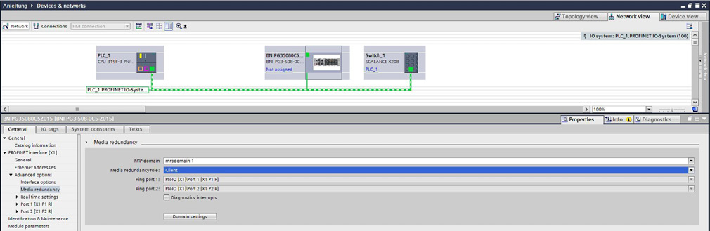
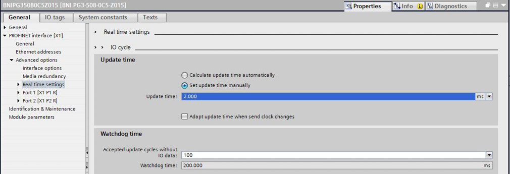
To ensure uninterrupted operation, the watchdog time should be greater than 200 milliseconds, as the MRP master requires some time to activate the second line. If the watchdog time is less than the switching time of the MRP master, this will cause a communication breakdown.
The watchdog time is calculated from the “Update time” and the Accepted update cycles without IO data factor.
Device Replacement without Exchangeable Medium
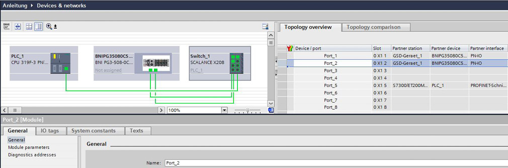
The modules also support simple device replacement in LLDP mode (Link Layer Discovery Protocol).
Activating Device Replacement without Exchangeable Medium
Before you begin
Make sure that:
The connected devices support LLDP (Link Layer Discovery Protocol).
The PROFINET network is physically wired, and the wiring matches the intended topology.
The PROFINET device has been added to the project and connected.
Steps
To activate device replacement without exchangeable medium in TIA Portal:
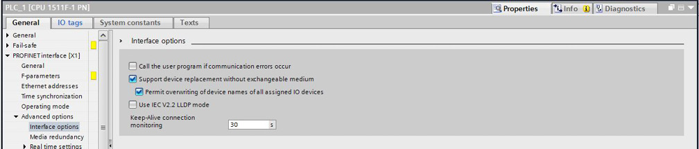
In the CPU hardware configuration, activate the Support device replacement without exchangeable medium checkbox.
Create the PROFINET topology in the hardware configuration.
Note
The connections of the individual ports must match the hardware wiring. If the topology in the hardware configuration is not a match, errors can occur.