Configuring Modules
The following modules can be assigned and configured:
Port module / IO-Link module (slot 1): Configures the IO-Link master and its eight ports. Each port can be assigned a submodule for a generic or preconfigured IO-Link device, or for digital input/output, together with port-level IO-Link parameters such as port mode, validation and backup, and the port quality index (PQI).
Extended Modules (slot 2): Optional Balluff-specific submodules that add diagnostic and configuration functionality beyond the basic port I/O, for example port/device event monitoring, network module settings, device alias configuration, IoT settings, and user management settings.
ISDU Parameter Configuration (slot 3): Submodules that write ISDU parameters to the connected IO-Link devices automatically whenever the PROFINET connection is established.
Port Modules
Slot 1 supports three module variants:
- IO-Link I/O Ports
The standard variant. The eight ports are mapped as subslots, and the module itself provides 1 input byte and 1 output byte for the digital Pin 2 I/O of all eight ports, so no additional submodules are needed to use basic Pin 2 digital I/O.
- IO-Link I/O Ports (w/o IO)
The same eight ports as IO-Link I/O Ports, but the module itself provides no input/output bytes (“w/o IO” = without IO data). To map Pin 2/4 digital I/O instead, use the Input Pin 2, Input Pin 4, Output Pin 2 and Output Pin 4 submodules, or the compact Inputs Pin 4 / Pin 2 - Port Mapping and Outputs Pin 4 / Pin 2 - Port Mapping submodules.
- IO-Link I/O Ports (w/o IO) with Safety Hub and ISDU
Same as IO-Link I/O Ports (w/o IO), but the number of port subslots is doubled: each port gets a second subslot for a safe communication, in addition to the subslot for its standard IO-Link submodule. Use this variant to integrate Balluff Safety Hub IO-Link devices (see Integrating Safety-Hub).
The following types of submodules are available for the subslots of the IO-Link modules in slot 1:
Digital Input/Output: Support basic digital input and output functionality for the ports, allowing direct mapping of Pin 2/4 signals.
IO-Link Generic Devices: Allow the integration of generic IO-Link devices by providing the necessary submodule for communication and configuration.
Preconfigured IO-Link Devices from Balluff: Provide ready-to-use submodules for specific Balluff IO-Link devices, simplifying integration and configuration.
The submodules can be assigned to each of the 8 subslots. The subslots represent the ports.
Digital Input and Digital Output Submodules
In order to configure the port pins to input or output, the corresponding submodule Digital Input or Digital Output must be dragged to the port. Pin 4 of the port is fixed by which submodule is used (input for Digital Input, output for Digital Output); Pin 2 is configured separately through the submodule’s own parameters.
Parameters
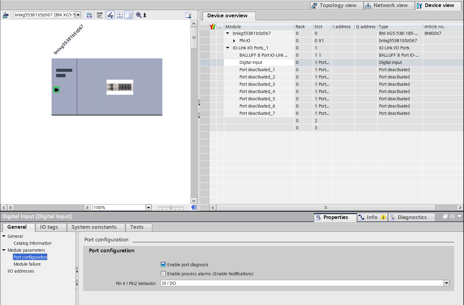
- Enable port diagnosis
Activates or deactivates the diagnostic messages of the port (static muting).
- Enable process alarms
Maps single-shot events (notifications) to process alarms.
- Pin 4 / Pin2 behavior
Pin 4 is fixed by the submodule used and cannot be changed. This setting only defines the behavior of Pin 2.
The following settings are possible (identical for Digital Input and Digital Output, the first part of the name reflects the plugged submodule):
DI/DO / NC: Pin 2 deactivated.
DI/DO / DI: Pin 2 digital input.
DI/DO / DO: Pin 2 digital output.
DI/DO / Power: Continuous voltage (actuator supply) on Pin 2.
Note
XG1 devices have no outputs to Pin 2.
Input Processdata
Where the Pin 2 and Pin 4 input data actually appears depends on which slot 1 module variant is plugged (see Port Modules):
IO-Link I/O Ports (with IO): Pin 2 of all 8 ports is combined into the module’s own input byte, one bit per port. Each plugged Digital Input submodule additionally provides its own 1 input byte for Pin 4 of that port:
0x00means low, any non-zero value (any bit set) means high.IO-Link I/O Ports (w/o IO): Neither the module nor the Digital Input submodule provide any process data (the submodule still only exposes the parameters above). Pin 2 and Pin 4 of all 8 ports must instead be read via the Input Pin 2 and Input Pin 4 submodules (or the combined Inputs Pin 4 / Pin 2 - Port Mapping submodule) in slot 2.
Output Processdata
The same applies to outputs:
IO-Link I/O Ports (with IO): Pin 2 of all 8 ports is combined into the module’s own output byte, one bit per port. Each plugged Digital Output submodule additionally provides its own 1 output byte for Pin 4 of that port:
0x00means low, any non-zero value (any bit set) means high.IO-Link I/O Ports (w/o IO): Neither the module nor the Digital Output submodule provide any process data. Pin 2 and Pin 4 of all 8 ports must instead be written via the Output Pin 2 and Output Pin 4 submodules (or the combined Outputs Pin 4 / Pin 2 - Port Mapping submodule) in slot 2.
Digital Input with IO-Link Parametrization
Digital Input with IO-Link Parametrization is a special variant of the Digital Input submodule for IO-Link SIO devices. Its parameters and process data are identical to the regular Digital Input submodule described above.
In normal operation, the port behaves exactly like a regular digital input.
However, when the PLC program uses the IOL_CALL function block to send an
ISDU request to the device on that port, the port is automatically switched
to IO-Link Autostart, the ISDU request is carried out, and the port then
falls back to digital input operation. This allows occasional ISDU access
(for example reading or writing a device parameter) on a port that is
otherwise used as a plain digital input.
IO-Link Generic Devices Submodules
Note
Please check whether IO-Link is supported by your module before using this function. For more information on product variants that support IO-Link, see Supported product variants.
The IO-Link Generic Devices submodules let a port exchange cyclic process data with any IO-Link device, independently of a specific device profile. A submodule is available for every combination of input and output process data length from 0 to 32 bytes (for example 1, 2, 4, 6, 8, 10, 16, 24, or 32 bytes), covering pure input, pure output, and combined input/output data. Each length combination is available both with and without the port quality index (PQI), see Port Quality Index (PQI).
Input and Output Processdata
Submodule names follow a naming pattern that encodes process data direction and length, with an optional PQI suffix:
IOL_I_<length>_ByteInput only. length is the number of input bytes, for example
IOL_I_01_Bytefor 1 input byte.IOL_O_<length>_ByteOutput only. length is the number of output bytes, for example
IOL_O_01_Bytefor 1 output byte.IOL_I/O_<in>/<out>_ByteInput and output. in and out are the number of input and output bytes, for example
IOL_I/O_08/08_Bytefor 8 input bytes and 8 output bytes.
Append + PQI to any of the names above to select the variant that also
includes the port quality index (PQI), for example IOL_I_01_Byte + PQI. See Port Quality Index (PQI) for more information about the port quality index.
Select the submodule whose input/output length matches the process data size of the connected IO-Link device (see the device’s IODD or manual) and drag it to the corresponding port subslot.
Parameters
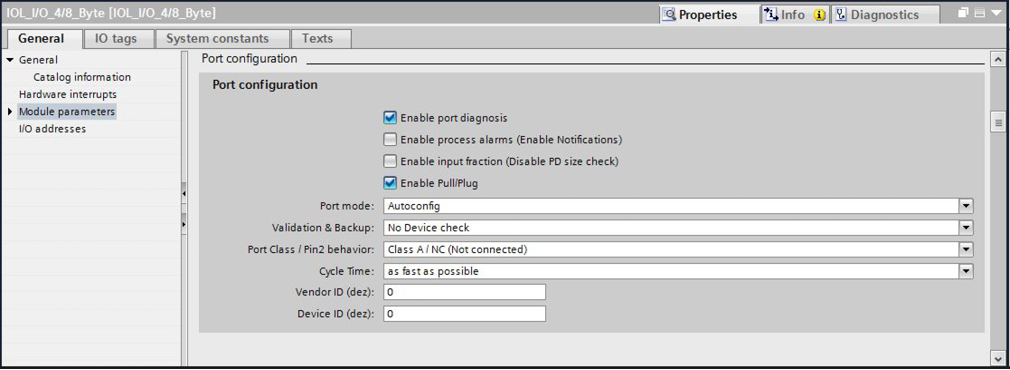
In the network module properties, the IO-Link parameters of the respective port can be changed.
Note
IO-Link configuration:
If the connected IO-Link device provides outputs, Pin 2 at the corresponding port must be configured as an output (see Port Quality Index (PQI)). Does not apply to XG1 devices.
The following parameters can be set:
- Enable port diagnosis
Activates or deactivates the diagnostic messages of the port (static muting).
- Enable process alarms
Maps single-shot events (notifications) to process alarms.
- Enable input fraction
Defines whether the input process data length of the connected IO-Link device is strictly checked against the configured submodule’s input length.
Disabled (default): The device’s input data length must be greater than or equal to the submodule’s input length, otherwise a process data mismatch diagnosis is raised.
Enabled: This check is skipped, so the device may provide less input data than the configured submodule length without raising a diagnosis.
Note
Only affects input process data. Output process data length is always checked.
- Enable Pull/Plug
Defines how the loss or return of a connected IO-Link device is reported: via PROFINET diagnosis (disabled), or via Pull/Plug (add/remove submodule), which triggers the PLC’s diagnostic interrupt OB82 (enabled).
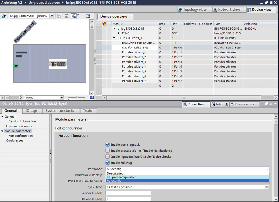
- Port mode
Defines the mode of the port.
The following settings are possible:
Deactivated: Switches the port off.
Set Port Config: Enables some settings to be changed manually, e.g. Cycle Time. Corresponds to the IO-Link master port mode IO-Link Manual.
Autoconfig: Activates IO-Link and the data exchange between master and device. Corresponds to the IO-Link master port mode IO-Link Autostart.
Note
Port mode must be set to Set Port Config to enable Validation & Backup (data storage), Vendor ID and Device ID.
- Validation & Backup
Used to identify specific or individual device types with which a data exchange should take place.
The following settings are possible:
No Device Check: Validation is deactivated and every device is accepted.
Compatibility Device V1.0: Only devices according to IOL specification 1.0 are accepted. No data storage, only validation active.
Compatibility Device V1.1: Only devices according to IOL specification 1.1 are accepted. No data storage, only validation active.
Compatibility Device V1.1 Backup and recovery: Only devices according to IOL specification 1.1 are accepted. Data storage with upload and download, with validation.
Compatibility Device V1.1 Recovery: Only devices according to IOL specification 1.1 are accepted. Data storage only with download (Master to Device), with validation.
Use together with Vendor ID and Device ID to restrict validation to a specific device type.
- Vendor ID
The decimal vendor ID of the IO-Link device expected at this port. Used together with Validation & Backup to restrict validation to devices from a specific vendor.
- Device ID
The decimal device ID of the IO-Link device expected at this port. Used together with Validation & Backup to restrict validation to this specific device type.
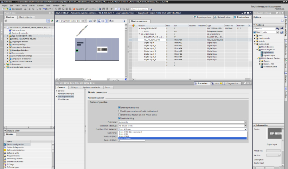
- Port Class / Pin2 behavior
Pin 4 behavior is always defined by the submodule plugged into the port. This setting only defines the behavior of Pin 2.
The following settings are possible (identical for Class A and Class B ports):
Class A/B / NC: Pin 2 deactivated.
Class A/B / DI: Pin 2 digital input.
Class A/B / DO: Pin 2 digital output.
Class A/B / Power: Continuous voltage (actuator supply) on Pin 2.
Note
Class B only available for devices with Class B property.
- Cycle Time
Makes it possible to influence the IO-Link communication speed, using the drop-down menu.
Port Quality Index (PQI)
Network modules are available with and without PQI. The PQI is 1 byte long and contains various information about the respective port status. This information can be found at the end of the input data of the submodule of a port for each bit.
The “Port Qualifier Information” (PQI) is a 1-byte status value that reports the status of an IO-Link port and the connected device.
The flags have the following meaning:
- PQ
Value
Description
0
Process data from device invalid
1
Process data from device valid
- DevErr
Value
Description
0
No errors/warnings
1
Errors/warnings occurred.
- DevCom
Value
Description
0
No device available
1
Device available
- PortActive
Value
Description
0
Port deactivated.
1
Port activated.
Note
Specification coverage: PQI is implemented according to IO-Link Integration for PROFINET (PI Order No. 2.832, Version 1.1 Edition 2, clause 7.3.4.2, Table 22). That specification additionally defines bit 2 (NewPar – a new Data Storage backup object became available after a Device parameter upload) and bit 3 (SubstDev – a substitute Device with a different serial number was detected). Both flags are currently not supported by this device family and are therefore always reported as reserved (“0”).
IO-Link Devices Submodules
The IO-Link Devices submodules provide ready-to-use, preconfigured submodules for specific Balluff IO-Link devices (for example sensors, IO-Link hubs, and BIS RFID devices) from the device catalog, identified by their exact product name, for example BNI IOL-709-000-XXXX.
Note
For Balluff Safety Hub IO-Link devices, use the IO-Link I/O Ports (w/o IO) with Safety Hub and ISDU module variant instead (see Integrating Safety-Hub).
Input and Output Processdata
Unlike the generic submodules (see IO-Link Generic Devices Submodules), where the process data length must be selected manually, the input and output process data length of a device catalog submodule is tailored exactly to the selected device, so no manual length matching is required.
Parameters
The parameters of a device catalog submodule contain the port configuration parameters (see Parameters) as well as the ISDU parameters of the selected device, taken from its IODD. This allows the device to be parameterized directly from the engineering tool for easy commissioning.
The ISDU parameters are forwarded to the device as ISDU write accesses and written to the device:
each time the IO-Link device is reconnected
for a new connection with the PLC
Usage
This section describes how to add a preconfigured IO-Link device submodule to a port.
Before you begin
Make sure that:
The GSDML file of the PROFINET device has been installed.
The IO-Link device to be used is connected to the port.
Steps
To add a preconfigured IO-Link device submodule in TIA Portal:
In the hardware catalog, select the desired device by its exact product name and drag it to the corresponding port subslot (slot 1).
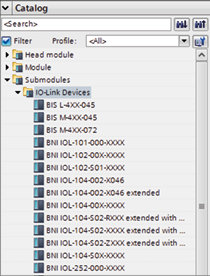
⇒ The device parameters appear in the module parameters of the corresponding port and can be selected.
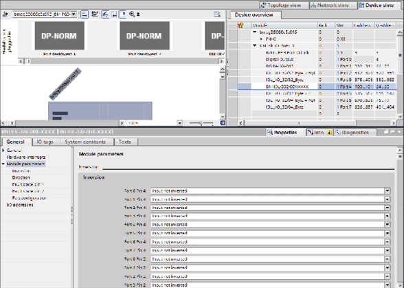
Extended Modules
In this chapter the modules are descriped which can be plugged into the extended slots of the device. Note that not all modules are available for all variants.
Input Pin 4
This module maps pin 4 of each port to an input bit, independently of the network module configured in slot 1.
Note
The IO-Link I/O Ports (w/o IO) module must be plugged into slot 1 (the port head slot) for this module to provide data.
Parameters
This module has no parameters.
Input Processdata
This module provides 1 input byte, one bit per port.
Bit 7 |
Bit 6 |
Bit 5 |
Bit 4 |
Bit 3 |
Bit 2 |
Bit 1 |
Bit 0 |
|---|---|---|---|---|---|---|---|
Port 8 |
Port 7 |
Port 6 |
Port 5 |
Port 4 |
Port 3 |
Port 2 |
Port 1 |
Output Processdata
This module has no Output Processdata.
Input Pin 2
This module maps pin 2 of each port to an input bit, independently of the network module configured in slot 1.
Note
The IO-Link I/O Ports (w/o IO) module must be plugged into slot 1 (the port head slot) for this module to provide data.
Parameters
This module has no parameters.
Input Processdata
This module provides 1 input byte, one bit per port.
Bit 7 |
Bit 6 |
Bit 5 |
Bit 4 |
Bit 3 |
Bit 2 |
Bit 1 |
Bit 0 |
|---|---|---|---|---|---|---|---|
Port 8 |
Port 7 |
Port 6 |
Port 5 |
Port 4 |
Port 3 |
Port 2 |
Port 1 |
Output Processdata
This module has no Output Processdata.
Output Pin 4
This module maps pin 4 of each port to an output bit, independently of the network module configured in slot 1.
Note
The IO-Link I/O Ports (w/o IO) module must be plugged into slot 1 (the port head slot) for this module to take effect.
Parameters
This module has no parameters.
Input Processdata
This module has no Input Processdata.
Output Processdata
This module provides 1 output byte, one bit per port.
Bit 7 |
Bit 6 |
Bit 5 |
Bit 4 |
Bit 3 |
Bit 2 |
Bit 1 |
Bit 0 |
|---|---|---|---|---|---|---|---|
Port 8 |
Port 7 |
Port 6 |
Port 5 |
Port 4 |
Port 3 |
Port 2 |
Port 1 |
Output Pin 2
This module maps pin 2 of each port to an output bit, independently of the network module configured in slot 1.
Note
The IO-Link I/O Ports (w/o IO) module must be plugged into slot 1 (the port head slot) for this module to take effect.
Note
XG1 devices have no outputs to Pin 2.
Parameters
This module has no parameters.
Input Processdata
This module has no Input Processdata.
Output Processdata
This module provides 1 output byte, one bit per port.
Bit 7 |
Bit 6 |
Bit 5 |
Bit 4 |
Bit 3 |
Bit 2 |
Bit 1 |
Bit 0 |
|---|---|---|---|---|---|---|---|
Port 8 |
Port 7 |
Port 6 |
Port 5 |
Port 4 |
Port 3 |
Port 2 |
Port 1 |
Pin1 Control
With this submodule, Pin 1 of each port can be switched off via process data.
Parameters
This module has one parameter.
Parameter |
Description |
Default |
|---|---|---|
Control Logic |
Defines whether a set output bit switches Pin 1 off or on |
|
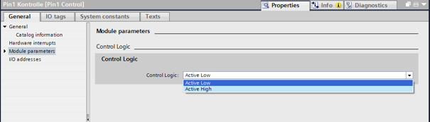
There are two selection options:
Value 0 – Active Low (default)
Output bit = 1 -> Pin 1 is OFF
Output bit = 0 -> Pin 1 is ON
Value 1 – Active High
Output bit = 1 -> Pin 1 is ON
Output bit = 0 -> Pin 1 is OFF
Input Processdata
This module has no Input Processdata.
Output Processdata
This module provides 1 output byte. Each bit switches Pin 1 of the corresponding port according to the configured Control Logic parameter.
Bit 7 |
Bit 6 |
Bit 5 |
Bit 4 |
Bit 3 |
Bit 2 |
Bit 1 |
Bit 0 |
|---|---|---|---|---|---|---|---|
Port 8 |
Port 7 |
Port 6 |
Port 5 |
Port 4 |
Port 3 |
Port 2 |
Port 1 |
Outputs Pin 4 / Pin 2 - Port Mapping
This module maps the Pin 4 and Pin 2 output command bits of all 8 ports into a compact 2-byte block instead of separate per-pin bytes. A set Pin 2 bit drives the port’s IQ output, and a set Pin 4 bit drives the port’s CQ output. The mapped bits are only applied when the port’s IOPS is good and the connection is in RUN, and only take effect on ports where the corresponding Output Pin 4/Output Pin 2 module allows it.
Note
The IO-Link I/O Ports (w/o IO) module must be plugged into slot 1 (the port head slot) for this module to take effect.
Parameters
This module has no parameters.
Output Processdata
This module provides 2 output bytes, 2 bits (Pin 4, Pin 2) per port, 4 ports per byte.
Byte 0 |
Bit 7 |
Bit 6 |
Bit 5 |
Bit 4 |
Bit 3 |
Bit 2 |
Bit 1 |
Bit 0 |
|---|---|---|---|---|---|---|---|---|
Port 4 Pin 2 |
Port 4 Pin 4 |
Port 3 Pin 2 |
Port 3 Pin 4 |
Port 2 Pin 2 |
Port 2 Pin 4 |
Port 1 Pin 2 |
Port 1 Pin 4 |
Byte 1 |
Bit 7 |
Bit 6 |
Bit 5 |
Bit 4 |
Bit 3 |
Bit 2 |
Bit 1 |
Bit 0 |
|---|---|---|---|---|---|---|---|---|
Port 8 Pin 2 |
Port 8 Pin 4 |
Port 7 Pin 2 |
Port 7 Pin 4 |
Port 6 Pin 2 |
Port 6 Pin 4 |
Port 5 Pin 2 |
Port 5 Pin 4 |
Input Processdata
This module has no Input Processdata.
Inputs Pin 4 / Pin 2 - Port Mapping
This module maps the Pin 4 and Pin 2 input state bits of all 8 ports into a compact 2-byte block instead of separate per-pin bytes. A set Pin 2 bit reflects the port’s IQ/readback logic, and a set Pin 4 bit reflects the port’s SMI input validity/data check. Each bit is only effective on ports where the corresponding Input Pin 4/Input Pin 2 module allows it.
Note
The IO-Link I/O Ports (w/o IO) module must be plugged into slot 1 (the port head slot) for this module to provide data.
Parameters
This module has no parameters.
Input Processdata
This module provides 2 input bytes, 2 bits (Pin 4, Pin 2) per port, 4 ports per byte.
Byte 0 |
Bit 7 |
Bit 6 |
Bit 5 |
Bit 4 |
Bit 3 |
Bit 2 |
Bit 1 |
Bit 0 |
|---|---|---|---|---|---|---|---|---|
Port 4 Pin 2 |
Port 4 Pin 4 |
Port 3 Pin 2 |
Port 3 Pin 4 |
Port 2 Pin 2 |
Port 2 Pin 4 |
Port 1 Pin 2 |
Port 1 Pin 4 |
Byte 1 |
Bit 7 |
Bit 6 |
Bit 5 |
Bit 4 |
Bit 3 |
Bit 2 |
Bit 1 |
Bit 0 |
|---|---|---|---|---|---|---|---|---|
Port 8 Pin 2 |
Port 8 Pin 4 |
Port 7 Pin 2 |
Port 7 Pin 4 |
Port 6 Pin 2 |
Port 6 Pin 4 |
Port 5 Pin 2 |
Port 5 Pin 4 |
Output Processdata
This module has no Output Processdata.
Pin 1 Short Circuit Detection
If a short circuit is detected at a port on pin 1, the corresponding bit is set to 1.
Parameters
This module has no parameters.
Input Processdata
This module provides 1 input byte, one bit per port.
Bit 7 |
Bit 6 |
Bit 5 |
Bit 4 |
Bit 3 |
Bit 2 |
Bit 1 |
Bit 0 |
|---|---|---|---|---|---|---|---|
Port 8 |
Port 7 |
Port 6 |
Port 5 |
Port 4 |
Port 3 |
Port 2 |
Port 1 |
Output Processdata
This module has no Output Processdata.
Pin 4/2 Actuator Ground Short Circuit Detection
If a short circuit is detected at a port on the pin, the corresponding bit is set to 1.
Parameters
This module has no parameters.
Input Processdata
This module provides 2 input bytes: Byte 0 reflects Pin 4 short circuit status and Byte 1 reflects Pin 2 short circuit status, one bit per port.
Byte 0 |
Bit 7 |
Bit 6 |
Bit 5 |
Bit 4 |
Bit 3 |
Bit 2 |
Bit 1 |
Bit 0 |
|---|---|---|---|---|---|---|---|---|
Port 8 Pin 4 |
Port 7 Pin 4 |
Port 6 Pin 4 |
Port 5 Pin 4 |
Port 4 Pin 4 |
Port 3 Pin 4 |
Port 2 Pin 4 |
Port 1 Pin 4 |
Byte 1 |
Bit 7 (15) |
Bit 6 (14) |
Bit 5 (13) |
Bit 4 (12) |
Bit 3 (11) |
Bit 2 (10) |
Bit 1 (9) |
Bit 0 (8) |
|---|---|---|---|---|---|---|---|---|
Port 8 Pin 2 |
Port 7 Pin 2 |
Port 6 Pin 2 |
Port 5 Pin 2 |
Port 4 Pin 2 |
Port 3 Pin 2 |
Port 2 Pin 2 |
Port 1 Pin 2 |
Output Processdata
This module has no Output Processdata.
Pin 4 IO-Link Short Circuit Detection
If an IO-Link short circuit is detected at a port on pin 4, the corresponding bit is set to 1. The port must be configured to IO-Link.
Parameters
This module has no parameters.
Input Processdata
This module provides 1 input byte, one bit per port.
Bit 7 |
Bit 6 |
Bit 5 |
Bit 4 |
Bit 3 |
Bit 2 |
Bit 1 |
Bit 0 |
|---|---|---|---|---|---|---|---|
Port 8 Pin 4 |
Port 7 Pin 4 |
Port 6 Pin 4 |
Port 5 Pin 4 |
Port 4 Pin 4 |
Port 3 Pin 4 |
Port 2 Pin 4 |
Port 1 Pin 4 |
Output Processdata
This module has no Output Processdata.
Pin 4/2 Actuator Warning Detection
If pin 2/4 of connection x (where x is a number between 1 and 8) is configured to:
OUTPUT (Pin 2/4)
If the voltage is low and an external voltage is applied, the bit is set to true.
If high-controlled (UA is missing; therefore the output is physically low) and an external voltage is applied, the bit is set to true.
POWER (Pin 2)
If UA is missing and external voltage is applied, the bit is set to true.
Parameters
This module has no parameters.
Input Processdata
This module provides 2 input bytes: Byte 0 reflects Pin 4 warning status and Byte 1 reflects Pin 2 warning status, one bit per port.
Byte 0 |
Bit 7 |
Bit 6 |
Bit 5 |
Bit 4 |
Bit 3 |
Bit 2 |
Bit 1 |
Bit 0 |
|---|---|---|---|---|---|---|---|---|
Port 8 Pin 4 |
Port 7 Pin 4 |
Port 6 Pin 4 |
Port 5 Pin 4 |
Port 4 Pin 4 |
Port 3 Pin 4 |
Port 2 Pin 4 |
Port 1 Pin 4 |
Byte 1 |
Bit 7 (15) |
Bit 6 (14) |
Bit 5 (13) |
Bit 4 (12) |
Bit 3 (11) |
Bit 2 (10) |
Bit 1 (9) |
Bit 0 (8) |
|---|---|---|---|---|---|---|---|---|
Port 8 Pin 2 |
Port 7 Pin 2 |
Port 6 Pin 2 |
Port 5 Pin 2 |
Port 4 Pin 2 |
Port 3 Pin 2 |
Port 2 Pin 2 |
Port 1 Pin 2 |
Output Processdata
This module has no Output Processdata.
Detection for Short Circuit and Actuator Warning
If an error with the following modules occurs, the corresponding bit is set to true:
Pin 1 Short Circuit Detection
Pin 4/2 Actuator Warning Detection
Pin 4/2 Actuator Ground Short Circuit Detection
Pin 4 IO-Link Short Circuit Detection
Parameters
This module has no parameters.
Input Processdata
This module provides 1 input byte, one bit per port.
Bit 7 |
Bit 6 |
Bit 5 |
Bit 4 |
Bit 3 |
Bit 2 |
Bit 1 |
Bit 0 |
|---|---|---|---|---|---|---|---|
Port 8 |
Port 7 |
Port 6 |
Port 5 |
Port 4 |
Port 3 |
Port 2 |
Port 1 |
Output Processdata
This module has no Output Processdata.
IO-Link Device Diagnosis Disable
Note
Please check whether IO-Link is supported by your module before using this function. For more information on product variants that support IO-Link, see Supported product variants.
If this function is configured, the IO-Link diagnosis remains activated for all ports and can be deactivated for the desired ports by setting the bit for the respective port.
Parameters
This module has no parameters.
Input Processdata
This module has no Input Processdata.
Output Processdata
This module provides 1 output byte, one bit per port.
Bit 7 |
Bit 6 |
Bit 5 |
Bit 4 |
Bit 3 |
Bit 2 |
Bit 1 |
Bit 0 |
|---|---|---|---|---|---|---|---|
Port 8 |
Port 7 |
Port 6 |
Port 5 |
Port 4 |
Port 3 |
Port 2 |
Port 1 |
IO-Link Communication
Note
Please check whether IO-Link is supported by your module before using this function. For more information on product variants that support IO-Link, see Supported product variants.
Bit status for each IO-Link port, i.e. feedback on whether communication has been established.
Parameters
This module has no parameters.
Input Processdata
This module provides 1 input byte, one bit per port.
Bit 7 |
Bit 6 |
Bit 5 |
Bit 4 |
Bit 3 |
Bit 2 |
Bit 1 |
Bit 0 |
|---|---|---|---|---|---|---|---|
Port 8 |
Port 7 |
Port 6 |
Port 5 |
Port 4 |
Port 3 |
Port 2 |
Port 1 |
Output Processdata
This module has no Output Processdata.
IO-Link PD Valid
Note
Please check whether IO-Link is supported by your module before using this function. For more information on product variants that support IO-Link, see Supported product variants.
Bit status for each IO-Link Port, i.e. feedback whether the process data at the corresponding port are set to Valid.
Parameters
This module has no parameters.
Input Processdata
This module provides 1 input byte, one bit per port.
Bit 7 |
Bit 6 |
Bit 5 |
Bit 4 |
Bit 3 |
Bit 2 |
Bit 1 |
Bit 0 |
|---|---|---|---|---|---|---|---|
Port 8 |
Port 7 |
Port 6 |
Port 5 |
Port 4 |
Port 3 |
Port 2 |
Port 1 |
Output Processdata
This module has no Output Processdata.
Module Diagnosis Disable
The Diagnostics Deactivated module allows various diagnostic messages sent by the module to be suppressed.
To deactivate the diagnostic messages:
Plug the Diagnosis Disable module into the extended modules (see Configurations of the Diagnosis Disable module).
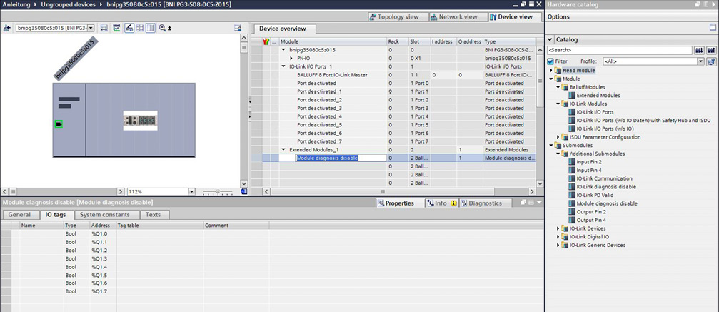
Parameters
This module has no parameters.
Input Processdata
This module has no Input Processdata.
Output Processdata
This module provides 1 output byte. The table below shows the individual bit fields and their possible values.
Pending diagnostics can be deleted at runtime by toggling the bit.
Port Event Pending
If an event is pending for a port, the corresponding bit is set to 1. If no event is pending for the port, the bit is set to 0. If multiple events were pending for a port, all of them must be cleared before the bit is reset to 0.
Parameters
This module has no parameters.
Input Processdata
This module provides 1 input byte, one bit per port.
Bit 7 |
Bit 6 |
Bit 5 |
Bit 4 |
Bit 3 |
Bit 2 |
Bit 1 |
Bit 0 |
|---|---|---|---|---|---|---|---|
Port 8 |
Port 7 |
Port 6 |
Port 5 |
Port 4 |
Port 3 |
Port 2 |
Port 1 |
Output Processdata
This module has no Output Processdata.
IO-Link Device Event Pending
If an IO-Link device event is pending at a port, the corresponding bit is set to 1. If no IO-Link device event is pending for the port, the bit is set to 0. If multiple events were pending for the port, all of them must be cleared before the bit is reset to 0.
Parameters
This module has no parameters.
Input Processdata
This module provides 1 input byte, one bit per port.
Bit 7 |
Bit 6 |
Bit 5 |
Bit 4 |
Bit 3 |
Bit 2 |
Bit 1 |
Bit 0 |
|---|---|---|---|---|---|---|---|
Port 8 |
Port 7 |
Port 6 |
Port 5 |
Port 4 |
Port 3 |
Port 2 |
Port 1 |
Output Processdata
This module has no Output Processdata.
Station Diagnosis
This module combines the diagnostic bits of several other Extended Modules — plus dedicated supply-voltage (US/UA) status bits — into a single 3-byte diagnostic block, instead of requiring each individual diagnostic module to be plugged in separately.
Parameters
This module has no parameters.
Input Processdata
This module provides 3 input bytes.
Byte 0 |
Bit 7 |
Bit 6 |
Bit 5 |
Bit 4 |
Bit 3 |
Bit 2 |
Bit 1 |
Bit 0 |
|---|---|---|---|---|---|---|---|---|
Reserved |
UA overvoltage |
UA undervoltage |
UA no voltage |
Reserved |
Reserved |
US overvoltage |
US undervoltage |
Byte 1 |
Bit 7 |
Bit 6 |
Bit 5 |
Bit 4 |
Bit 3 |
Bit 2 |
Bit 1 |
Bit 0 |
|---|---|---|---|---|---|---|---|---|
Pin 4 IO-Link short circuit |
Pin 2 actuator-supply warning |
Pin 4 actuator-supply warning |
Reserved |
Reserved |
Pin 2 actuator-ground short circuit |
Pin 4 actuator-ground short circuit |
Pin 1 short circuit |
Byte 2 |
Bit 7 |
Bit 6 |
Bit 5 |
Bit 4 |
Bit 3 |
Bit 2 |
Bit 1 |
Bit 0 |
|---|---|---|---|---|---|---|---|---|
Reserved |
Reserved |
IO-Link device event pending |
PD invalid summary |
Reserved |
Reserved |
Reserved |
Port event pending |
Byte 1’s bits mirror the Pin 1 Short Circuit Detection, Pin 4/2 Actuator Ground Short Circuit Detection, Pin 4/2 Actuator Warning Detection, and Pin 4 IO-Link Short Circuit Detection modules; Byte 2’s bits mirror the Port Event Pending and IO-Link Device Event Pending modules, plus a summary PD-invalid bit.
Output Processdata
This module has no Output Processdata.
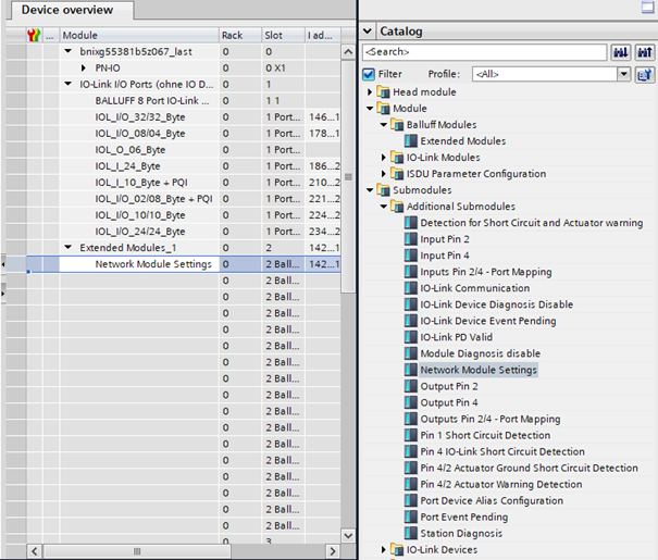
Network Module Settings
Note
This module is only available for the XG5-538-…-variants.
The network module settings module in the extended Balluff PROFINET submodules allows the behavior of the IO-Link master outputs to be influenced in the event of a sudden loss of actuator voltage UA. The configured setting is saved permanently — the module can be inserted, configured, and afterwards removed; the setting will be retained.
Parameters
This module has one parameter.
Parameter |
Description |
Default |
|---|---|---|
UA Power Setting |
Defines what happens to active outputs on Pin 2 and Pin 4 when UA voltage is lost |
|
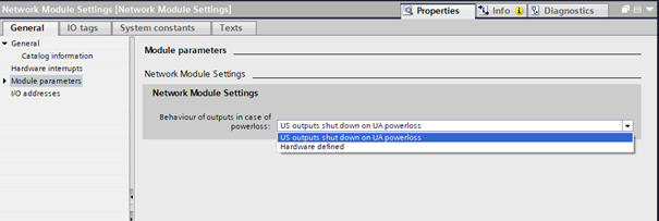
There are two selection options:
Value 0 – US Outputs shutdown on UA powerloss
All active outputs on Pin 2 and Pin 4 are automatically switched off in the event of a UA voltage drop. This matches the behavior of a XG5-508-… master, even though Pin 2 and Pin 4 of Class A output ports are supplied by US, and Pin 4 of Class B ports are supplied by UA.
Value 1 – Hardware Defined
US powered outputs will not be switched off in the event of a UA voltage drop. All outputs remain in their current state. Only Class B Pin 2 outputs are physically supplied by UA and will therefore be shut down.
Input Processdata
This module provides 4 input bytes reflecting the currently active value of the UA Powerloss behavior Setting parameter.
Bit 7 |
Bit 6 |
Bit 5 |
Bit 4 |
Bit 3 |
Bit 2 |
Bit 1 |
Bit 0 |
|
|---|---|---|---|---|---|---|---|---|
Byte 0 |
Reserved |
Read Value Enum UA Powerloss Behavior |
||||||
Byte 1 |
Reserved |
|||||||
Byte 2 |
Reserved |
|||||||
Byte 3 |
Reserved |
|||||||
Output Processdata
This module has no Output Processdata.
Port Device Alias Configuration
With this submodule, an individual device alias can be assigned to each port. The device alias is used by the REST API and is shown in the WebUI.
Note
Since the device alias is saved permanently, this module can be removed from the configuration again after it has been configured successfully.
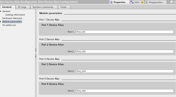
Parameters
This module has 8 parameters, one device alias per port (max. 32 characters each).
Parameter |
Description |
Default |
|---|---|---|
Port 1 Device Alias |
Device alias for Port 1 |
|
Port 2 Device Alias |
Device alias for Port 2 |
|
Port 3 Device Alias |
Device alias for Port 3 |
|
Port 4 Device Alias |
Device alias for Port 4 |
|
Port 5 Device Alias |
Device alias for Port 5 |
|
Port 6 Device Alias |
Device alias for Port 6 |
|
Port 7 Device Alias |
Device alias for Port 7 |
|
Port 8 Device Alias |
Device alias for Port 8 |
|
Input Processdata
This module provides 8 input bytes, one status byte per port, reporting the result of the alias assignment for that port.
Byte 0 |
Byte 1 |
Byte 2 |
Byte 3 |
Byte 4 |
Byte 5 |
Byte 6 |
Byte 7 |
|---|---|---|---|---|---|---|---|
Port 1 |
Port 2 |
Port 3 |
Port 4 |
Port 5 |
Port 6 |
Port 7 |
Port 8 |
Each status byte can have the following values:
Value |
Description |
|---|---|
|
SUCCESS |
|
TOO_LONG |
|
NOT_UNIQUE |
|
ERROR |
Output Processdata
This module has no Output Processdata.
IoT Settings
With this submodule, the WebUI, the REST API, and the HTTP/HTTPS transfer protocol can be enabled or disabled.
Note
Since the settings are saved permanently, this module can be removed from the configuration again after it has been configured successfully.
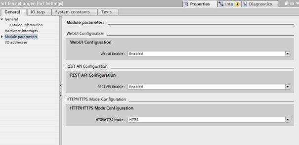
Parameters
This module has 3 parameters.
Parameter |
Description |
Default |
|---|---|---|
WebUI Enable |
Enables or disables the WebUI |
|
REST API Enable |
Enables or disables the REST API |
|
HTTP/HTTPS Mode |
Defines which transfer protocol is used |
|
There are two selection options for WebUI Enable and REST API Enable:
Value 0 – Disabled
Value 1 – Enabled
There are four selection options for HTTP/HTTPS Mode:
Value 0 – None
Value 1 – HTTP
Value 2 – HTTPS
Value 3 – HTTP and HTTPS
Note
The three parameters depend on each other. If REST API Enable or HTTP/HTTPS Mode is set to disabled/none, WebUI Enable is forced to disabled as well. If WebUI Enable is set to enabled, REST API Enable is forced to enabled; if no transfer protocol is active in this case, HTTPS is enabled automatically.
Input Processdata
This module provides 5 input bytes, reflecting the currently active values.
Byte 0 |
Byte 1 |
Byte 2 |
Byte 3 |
Byte 4 |
|---|---|---|---|---|
WebUI Status |
Reserved |
REST API Status |
Transfer Protocol |
Reserved |
WebUI Status and REST API Status can have the following values:
Value |
Description |
|---|---|
|
Disabled |
|
Enabled |
Transfer Protocol can have the following values:
Value |
Description |
|---|---|
|
None |
|
HTTP |
|
HTTPS |
|
HTTP and HTTPS |
The reserved bytes (Byte 1 and Byte 4) are always 0.
Output Processdata
This module has no Output Processdata.
User Management Settings
With this submodule, the authentication mode and session timeouts for the BNI user management can be configured, and the password of an existing user can be updated.
Note
The configured authentication mode and session timeouts are saved permanently. This module can be removed from the configuration again after it has been configured successfully.
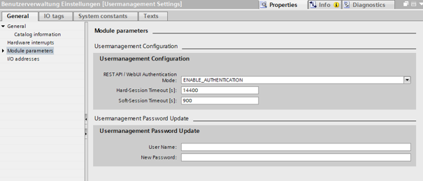
Parameters
This module has 2 parameter records.
User Management Configuration
Parameter |
Description |
Default |
|---|---|---|
Authentication Mode |
Defines the REST API / WebUI authentication mode |
|
Hard-Session Timeout [s] |
Session timeout in seconds |
|
Soft-Session Timeout [s] |
Session timeout in seconds |
|
There are two selection options for Authentication Mode:
Value 0 – Disable REST API Authentication (WebUI authentication remains active)
Value 2 – Enable Authentication
User Management Password Update
Note
This module can only update the password of an already existing user. It is not possible to create a new user through this module.
Parameter |
Description |
Default |
|---|---|---|
User Name |
User name of the existing user whose password is updated (max. 64 characters) |
(empty) |
New Password |
New password for the given user (max. 255 characters) |
(empty) |
Input Processdata
This module provides 9 input bytes, reporting the result of the last password update.
Byte 0-7 |
Byte 8 |
|---|---|
User Id |
Status |
User Id (Byte 0-7) contains the resulting user Id, zero-padded if shorter than 8 characters, on a successful password update. On failure it is usually all zeros, though for some failures after the user has been found it may still be returned together with the error status; for User Not Found it is always cleared to zero.
Status (Byte 8) can have the following values:
Value |
Description |
|---|---|
|
OK |
|
User Not Found |
|
Invalid Input |
|
Operation Failed |
Output Processdata
This module has no Output Processdata.
ISDU Module
With ISDU parameterization via GSDML, the connected IO-Link devices can be configured via the parameters of the corresponding submodules when establishing a connection with PROFINET.
The parameters are transferred when the BNI establishes the connection with the controller and are then forwarded directly to the corresponding IO-Link devices as ISDU write accesses. When an IO-Link device is unplugged and plugged in, the ISDU parameters configured in advance and transmitted by the controller are written again.
Parameters
The following settings exist for the ISDU parameterization:
Reset to factory defaults: Resets the ISDU parameters to factory settings. The ISDU parameters can then be reset.
Start block parameterization: Starts the check of several parameters of a device. The parameters are checked for plausibility only at the end of the complete parameterization.
End block parameterization: Ends the check of the parameters of a device. Setting the parameter is mandatory if Start block parameterization has been selected.
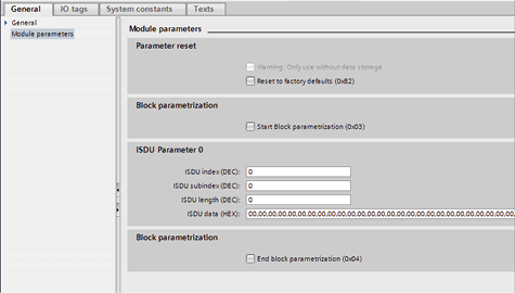
In addition, each submodule provides a fixed number of ISDU parameter entries (Index, Subindex, Length, and Data), one per parameter to be written to the IO-Link device. Six ISDU Parameter Configuration submodules are available, differing only in the number of entries they provide:
Submodule |
ISDU parameter entries |
|---|---|
ISDU 1 Parameter |
1 |
ISDU 4 Parameter |
4 |
ISDU 8 Parameter |
8 |
ISDU 16 Parameter |
16 |
ISDU 32 Parameter |
32 |
ISDU 64 Parameter |
64 |
Select the submodule that provides enough entries for the number of ISDU parameters to be written to the connected device.
Input Processdata
This module has no Input Processdata.
Output Processdata
This module has no Output Processdata.
Usage
This section describes how to configure ISDU parameterization via GSDML for a port.
Before you begin
Make sure that:
The GSDML file of the PROFINET device has been installed.
An IOL submodule has been plugged into the desired port (slot 1).
See: Port Modules.
An IO-Link device is connected to the port.
Steps
To carry out ISDU parameterization in TIA Portal:
Insert the ISDU parameter configuration module into slot 3.
Select one of the six ISDU Parameter Configuration submodules (see Parameters above) that provides enough entries for the connected device, and insert it into the subslot that corresponds to the port to be parameterized.
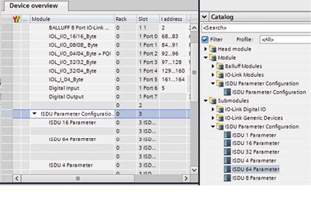
The subslots of the ISDU Parameter Configuration module correspond to the IO-Link ports in the same order: the first port’s submodule corresponds to the first ISDU subslot, the second port’s submodule to the second ISDU subslot, and so on.
Note
Unlike the IO-Link ports in slot 1, where the first subslot is reserved for the IO-Link Proxy itself (shifting the port subslots by one), the ISDU Parameter Configuration module in slot 3 has no such offset: its subslots map directly to the ports, in the same order.
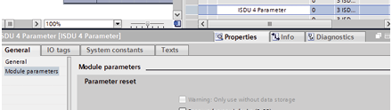
Enter the ISDU parameters in the corresponding fields.
Note
Regardless of the submodule used, only the parameters that are entered are written to the IO-Link device (condition: length > 0). When the connection is established, all parameters are transferred to the BNI.
Example
ISDU 64 parameter is plugged in and 5 ISDU parameters are described.
All 64 parameters are transferred when the connection is established.
Only the 5 described ISDU parameters are transferred to the device.