PROFINET Module Basics
This chapter describes how the device’s GSDML maps onto PROFINET slots, subslots, modules, and submodules. The illustrations are taken from the Totally Integrated Automation Portal (TIA Portal) and from SIMATIC Manager (Siemens AG) and are for reference only.
The BNI XG5-538-1B5-Z067 (order code BNI00K7) is used as the reference device throughout this chapter, consistent with the rest of this documentation. Other variants use the same slot/subslot/module/submodule model but may offer a different number of ports or a different set of modules per slot (for example, whether a Safety Hub module is available).
Device Model
TIA represents the device model as follows:
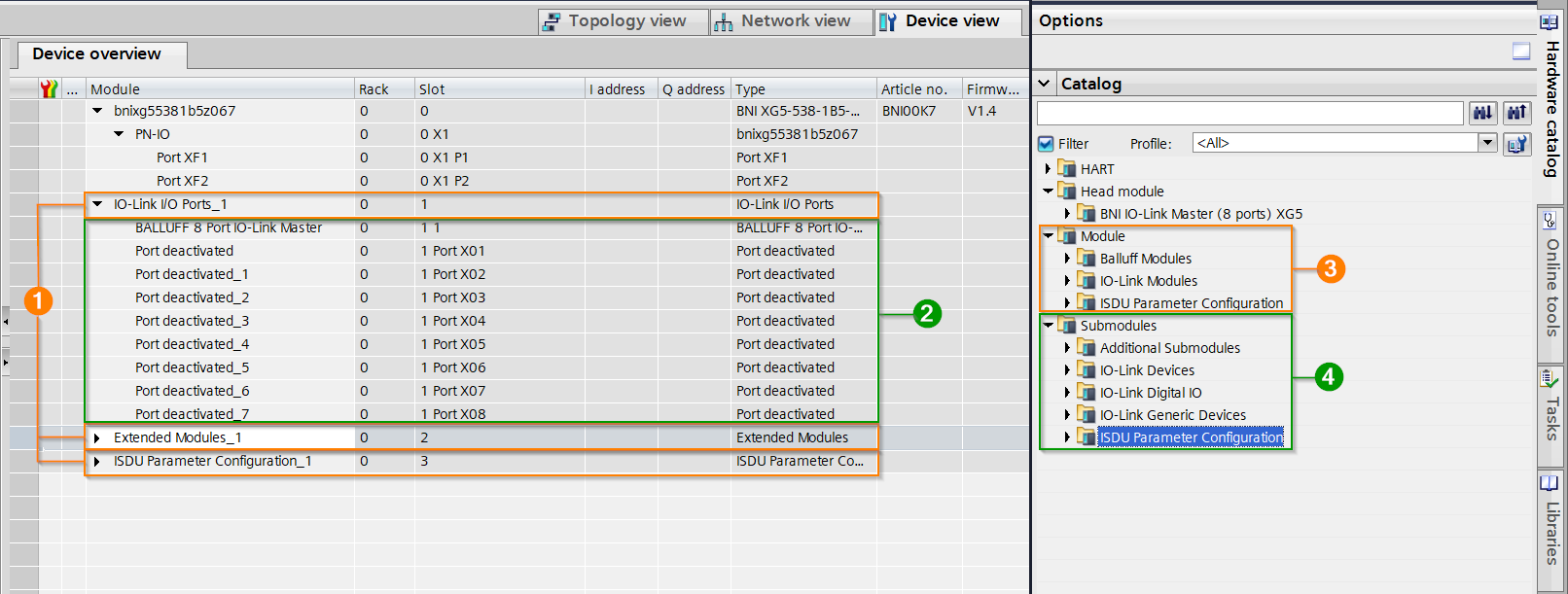
No. |
Description |
|---|---|
1 |
Slots |
2 |
Subslots |
3 |
Modules |
4 |
Submodules |
Slot Layout
The PROFINET device uses four slots (0–3). Slot 0 is the fixed head module and represents the BNI device itself. The PROFINET interface (PN-IO) is nested beneath it as subslot X1, and the two device ports are nested beneath the interface as subslots X1 P1 and X1 P2:
Module |
Slot |
||
|---|---|---|---|
Head module (BNI device) |
0 |
||
PN-IO (PROFINET interface) |
0 X1 |
||
Port XF1 (Port 1) |
0 X1 P1 |
||
Port XF2 (Port 2) |
0 X1 P2 |
||
Slot 1 is mandatory and pre-assigned the IO-Link I/O Ports module by default. It represents the IO-Link interface: the IO-Link Proxy and the eight IO-Link ports are mapped as subslot 1 and subslots X01 to X08:
Module |
Slot |
|
|---|---|---|
IO-Link I/O Ports |
1 |
|
IO-Link Proxy (BALLUFF 8 Port IO-Link Master) |
1 1 |
|
Port 1 |
1 X01 |
|
Port 2 |
1 X02 |
|
Port 3 |
1 X03 |
|
Port 4 |
1 X04 |
|
Port 5 |
1 X05 |
|
Port 6 |
1 X06 |
|
Port 7 |
1 X07 |
|
Port 8 |
1 X08 |
|
Slot 1 supports three module variants:
IO-Link I/O Ports
IO-Link I/O Ports (w/o IO)
IO-Link I/O Ports (w/o IO) with Safety Hub and ISDU
Refer to Port Modules for more information on configuring the port modules.
Slots 2 and 3 are optional and are not assigned a module by default.
Slot 2 represents the extended modules. Refer to Extended Modules for more information on configuring the extended modules.
Slot 3 represents the ISDU parameter configuration modules; each subslot represents an IO-Link port. Refer to ISDU Module for more information on configuring the ISDU modules.