SSI output configuration
Description
The behavior of the SSI interface can be configured via IO-Link. Normally the SSI supports only one output data but with this product additional data can be enabled that follows directly after the main data.
Some properties of the additional data can be configured independently, though with limited options.
Main data
This is the primary data for the SSI output. This data is transmitted first (the length is determined by the SSI configuration parameter Number of bits).
The following is available as main data:
Position of the first position magnet
Position difference
Additional data
If the SSI additional data enable parameter is set to true, the selected data is inserted after the main data.
The following is available as additional data:
Position of the second position magnet
Velocity of the first position magnet (signed)
Velocity of the first position magnet (absolute)
Position difference
Internal temperature
Movement distance
Total operating time
ISDU
SSI output data selector
Value |
Meaning |
|---|---|
0x00 (0) |
Position of position magnet 1 |
0x04 (4) |
Position difference |
SSI configuration
Coding
This parameter is used to select between binary and Gray coding. It affects both the encoding of the main data and that of the supplementary data, however with Gray coding the two values are coded seperately.
Value |
Meaning |
|---|---|
0x00 (0) |
Binary |
0x01 (1) |
Gray |
Representation
Selects between two’s complement and sign and magnitude representations. This parameter affeccts both main and additional data’s representation.
Value |
Meaning |
|---|---|
0x00 (0) |
Two’s complement |
0x01 (1) |
Sign and magnitude |
Parity mode
Controls the parity bit mode for the main data only.
Value |
Meaning |
|---|---|
0x00 (0) |
Parity disabled |
0x01 (1) |
Even parity |
0x02 (2) |
Odd parity |
Note
Enabling the parity bit reduces the number of bits available for the main data.
For example if the Number of bits is set to 24 and the parity bit is enabled (even or odd), the remaining 23 bits are used to represent the actual value.
Note
When parity is enabled, it is always the MSB.
Error bit enable
If the parameter is set to true, an error bit is inserted before the main data.
Note
Enabling the error bit reduces the number of bits available for the main data.
For example if the Number of bits is set to 24 and the error bit is enabled, the remaining 23 bits are used to represent the actual value.
Multiple transmission enable
Set this parameter to true to enable multiple transmission. For more details see operation principle.
Adaptive timeout enable
If adaptive timeout is disabled, the monoflop timeout is set to Timeout. If adaptive timeout is enabled, the monoflop timeout is derived from the SSI clock frequency (twice the clock period).
For details, see operation principle.
Invert
This parameter inverts the output characteristic.
Note
Invert is only for position data.
Number of bits
This field specifies that how many bits are used to represent the main data. The Number of bits must be between 16 and 32 (inclusive) and can be configured in increments of 1 bit. If the additional data is enabled, the total number of bits must be less than or equal to 48.
Note
The Number of bits includes the error and / or parity bit if enabled.
For example: to have 24 bit position data with error and parity bit, the Number of bits parameter must be set to 26.
Timeout
Specifies the SSI monoflop timeout in microseconds (μs). This value must be between 1 and 500 μs (inclusive).
Hysteresis
Specifies the position hysteresis. The unit is micrometer (μm). The value must be between 0 and 10.000 (inclusive).
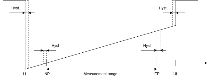
Error value
This parameter defines the substitution value if there is an error condition or the measurement value is below lower limit (LL) or upper limit (UL).
By default it is the largest 32 bit positive integer.
SSI resolution
Available resoltion modes:
Value |
Resolution |
|---|---|
0x00 (0) |
100 nm |
0x01 (1) |
500 nm |
0x02 (2) |
1 μm |
0x03 (3) |
2 μm |
0x04 (4) |
5 μm |
0x05 (5) |
10 μm |
0x06 (6) |
20 μm |
0x07 (7) |
40 μm |
0x08 (8) |
50 μm |
0x09 (9) |
100 μm |
SSI offset
This parameter is an optional offset value for the main data.
Note
The offset is used for the following data only:
Position of the first position magnet
Position difference
The offset for all the other data is ignored.
SSI additional data enable
Enables the additional data that follows immediately the main data.
SSI additional data selector
Note
If Multiplexer data option is enabled, the state of the two digital inputs determines which value is set as additional data. Not all variant supports this mode.
Note
The unit for Movement distance and Device operating time depends on the number of bits used for the additional data.
For more information, see Additional data and multiplexer input section.
SSI additional data configuration
Invert
This parameter reverses the output characteristic curve.
Note
Invert is only available for position data.
Number of bits
This field specifies how many bits are used to represent the additional data.
Only the following options are available:
Value |
Meaning |
|---|---|
0x08 (8) |
8 bit |
0x10 (16) |
16 bit |
0x18 (24) |
24 bit |
Note
The following values are not available in 8 bit mode:
Position of the second magnet
Velocity of the first position magnet (signed)
Velocity of the first position magnet (absolute)
Position difference
The following values are not available in 24 bit mode:
Internal temperature
Movement distance
Device operating hours
Multiplexer data
Hysteresis
This parameter specifies the position or velocity hysteresis. The unit is μm (position data) or 0.1 mm/s (velocity data).
The value must be between 0 and 10.000 (inclusive), see Hysteresis.
Error value
This parameter defines the substitution value when an error condition occurs. By default, it is the largest 32 bit positive integer.
SSI additional data resolution
This parameter controls the additional data resolution. See SSI resolution for available options.
Note
This parameter controls the resolution for the following additional data:
Position of the second position magnet
Position difference
The resolution for all the other additional data modes is fixed.
SSI additional data offset
This parameter is an optional offset value for the additional data.
Note
The offset is used for the following data only:
Position of the second position magnet
Position difference
The offset for all the other data is ignored.
Additional data and multiplexer input
In case of Movement distance and Device operating time the unit depends on the SSI additional data configuration - Number of bits field.
Number of bits |
Unit |
|---|---|
0x08 (8) |
1000 km |
0x10 (16) |
km |
Number of bits |
Unit |
|---|---|
0x08 (8) |
1000 hours |
0x10 (16) |
24 hours (day) |
The unit for Internal temperature is °C.
When the additional data selector is set to Multiplexer input, the two digital inputs of the BTL selects between the following additional data values:
La |
Lb |
Meaning |
|---|---|---|
LOW (0) |
LOW (0) |
Additional data disabled |
LOW (0) |
HIGH (1) |
Internal temperature |
HIGH (1) |
LOW (0) |
Movement distance |
HIGH (1) |
HIGH (1) |
Device operating time |