Switching signal channel
The sensor implements SSP 2.8 profile according to the IO-Link specification. In this profile there are four switching channels are available:
SSC1.1
SSC1.2
SSC1.3
SSC1.4
Note
The implemented profile requires a Process Data In byte, so that these switching signals are available in the process data. For details see Process Data In structure.
However it is not recommended to use those signals for any purpose as this sensor is primarily an SSI sensor. These signals are mainly used in the Stroke monitoring function.
Description
Evaluation logic
The sensor performs measurement value acquisition as a continous signal that is avaluated for switching signal generation. The measurement value is only evaluated if it is within this valid measurement range. If the measurement value is outside of this range, the switching channel output goes into inactive state.
Note
The switching channel output signal (high or low) depends on the channel configuration.
In case of BTL the measurement signal is always the position of the first position magnet.
Switching points are defined by means of setpoints that can be determined using teach process. Alternatively, the setpoints can also be set directly via ISDUs, but under observation of the same requirements and rules as define for the teach process.
The setpoint setting can also be used to deactivate the switching point evaluation.
Value |
Meaning |
|---|---|
0x7FFFFFFC (2,147,483,644) |
Setpoint not taught, disabled |
Overview of switching signal channels
Switchpoint logic
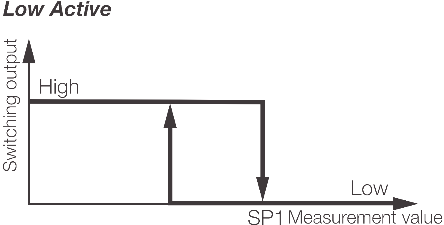
With switching logic High Active, the switching output switches to high if the current measurement value is greater than the set (taught) setpoint.
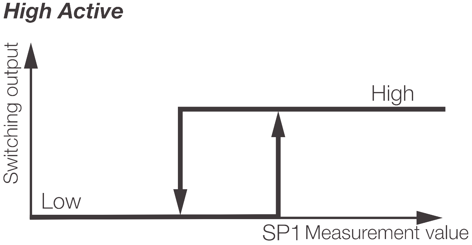
With Low Active this logic is inverted.
Switchpoint mode
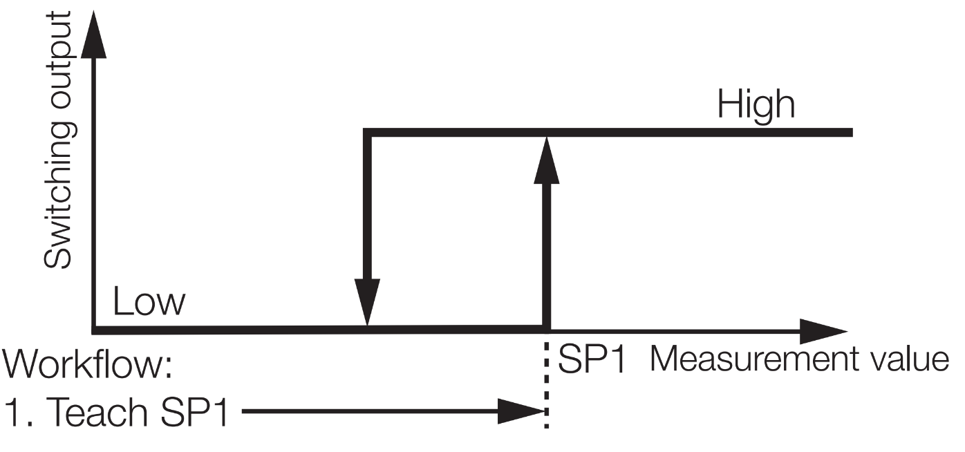
Single point mode
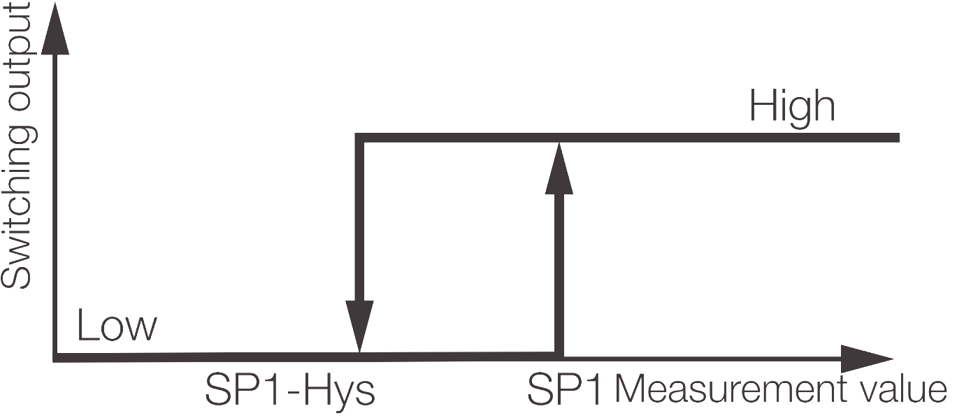
In single point mode, only one switching point (setpoint) is defined.
Switching behavior:
Measurement value ≥ switching point: output active
Measurement value ≤ switching point minus a defined hysteresis: output inactive
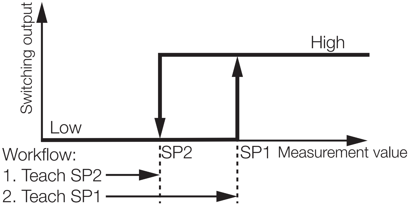
Two point mode
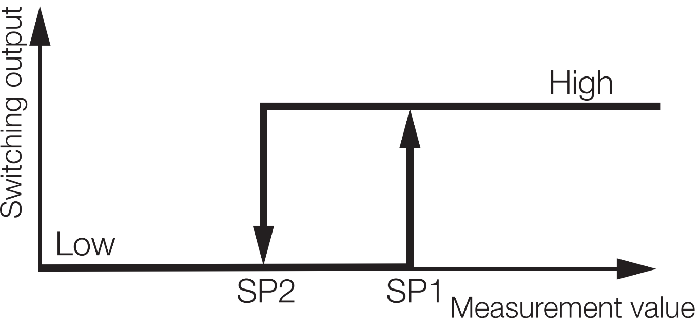
In two point mode, two switching points (setpoint) are defined.
Switching behavior:
Measurement value ≥ switching point 1: output active
Measurement value ≤ switching point 2 output inactive
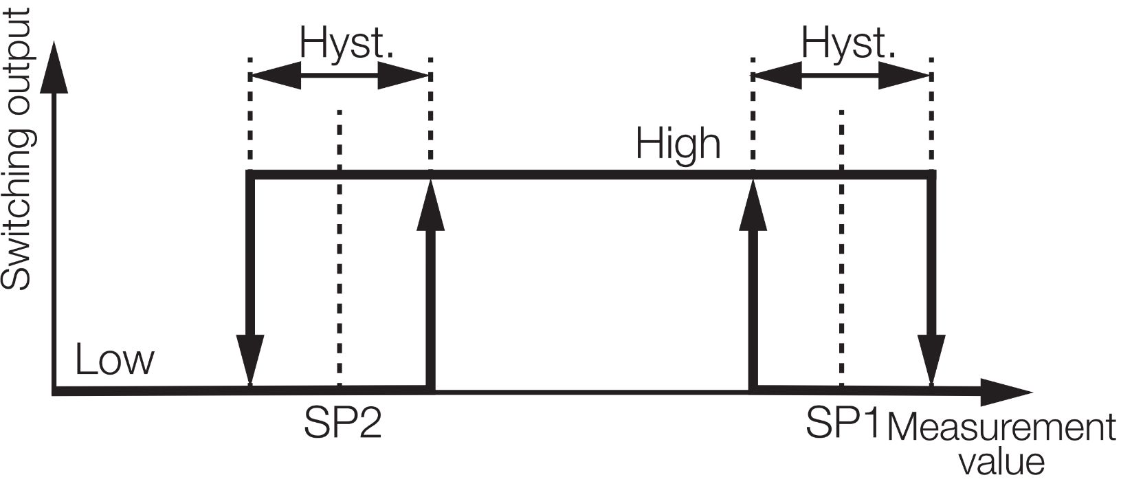
Window mode
In window mode, two switching points (setpoints) are defined.
Switching behavior:
If the output is inactive and the measurement value is greater than or equal to switching point 2 + 50% of the set hysteresis or the measurement value is less than or equal to switching point 1 – 50% of the set hysteresis, the output switches to active.
If the output is active and the measurement value is less than or equal to switching point 2 – 50% of the set hysteresis or the measurement value is greater than or equal to switching point 1 + 50% of the set hysteresis, the output switches to inactive.
Teaching
Single value teach
With Single-Value Teach, the switching point (setpoint) is defined via a teach point. Moreover, this is a static process, i.e., the measurement value is constant during the teach phase. The teach process is performed independently for each switching point in two point mode.
ISDU
Teach-in select
With the help of this parameter, the switching channel that is to be taught is selected.
SSC |
Value |
|---|---|
Default (SSC 1.1) |
0x00 (0) |
SSC 1.1 |
0x01 (1) |
SSC 1.2 |
0x02 (2) |
SSC 1.3 |
0x03 (3) |
SSC 1.4 |
0x04 (4) |
Teach-in result
Outputs the current status of the currently active or of the last teach-in process.
SSC 1.x configuration
Switchpoint logic
This parameter controls the logical output value of a switching signal channel.
Logic |
Value |
|---|---|
High active |
0x00 (0) |
Low active |
0x01 (1) |
Switchpoint mode
Logic |
Value |
|---|---|
Deactivated |
0x00 (0) |
Single point |
0x01 (1) |
Window |
0x02 (2) |
Two point |
0x03 (3) |
Hysteresis
Switchpoint hysteresis in μm. The actual usage of this value is depends on the Switchpoint mode.
SSC 1.x parameter
This ISDU contains two setpoints which defines the switching characteristic according to the channel’s mode. Setpoint 2 is not relevant if the channel mode is Disabled or Single point.