Product description
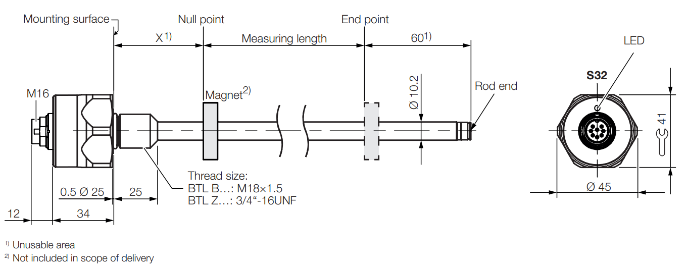
Type |
X |
Rod end |
|---|---|---|
BTL_NCA… |
30 - 1 mm |
with thread M4/4.5 deep |
BTL_NCE… |
2“ - 0.04“ |
with thread M4/4.5 deep |
Construction
Electrical connection: The electrical connection is made via a plug connection (see Type code).
Housing: Housing containing the processing electronics.
Fastening: We recommend assembling the following BTLs on the mounting thread:
BTL B…: M18×1.5
BTL Z…: 3/4“-16UNF
There is an additional thread at the end of the rod to support large measuring lengths.
Position magnet: Defines the position to be measured on the waveguide. Position magnets are available in various models and must be ordered separately (see Accessories).
Measuring length: Defines the travel/length range available. Sensors with measuring lengths from 25 mm to 5000 mm are available.
Function
To determine the position of a plant component, a position magnet is connected to the component. Together they are moved along a waveguide located inside the BTL.
An internally generated INIT pulse interacts with the magnetic field of the position magnet to generate a torsional wave in the waveguide which propagates at ultrasonic velocity. The component of the torsional wave which arrives at the end of the waveguide is absorbed in the damping zone to prevent reflection. The component of the torsional wave which arrives at the beginning of the waveguide is converted by a coil into an electrical signal. The position of the position magnet and thus at the same time that of the plant component is determined from the running time of the shaft.
Up to 2 position magnets can be used for FMM (Flexible Magnet Mode).
The following functions can be selected for the output values:
Position
Velocity
Position difference
The product supports following interfaces:
The primary interface SSI is intended for the transmission of operating data.
The IO-Link interface is used exclusively for product configuration and maintenance.
To avoid interference with SSI communication, the SSI and IO-Link interface must not be used simultaneously!
The full range of functions can be configured using the “Balluff Engineering Tool” (BET) PC software.
Note
To configure the device via IO-Link, an IO-Link master must be connected.
Display elements
The product support the following display elements:
The status LED displays its operating status. See LED interface for details.
Part label

Element |
Description |
|---|---|
1) |
Order code |
2) |
Type |
3) |
Serial number |
Type code
Example |
BTL |
BNCA00 |
- |
0500 |
- |
C15DUA01 |
- |
000S32 |
Definition |
BTL |
aNCb00 |
- |
cccc |
- |
C15defgh |
- |
000S32 |