Stroke monitoring
The stroke monitoring feature contains the following components:
Distance counter
Stroke counter
Deviation monitoring
This feature supports up to 3 independent stroke channels. Each channel can be configured and enabled separately. A stroke channel is determined by the start and end switching point. One switching point can be used in multiple stroke channels.
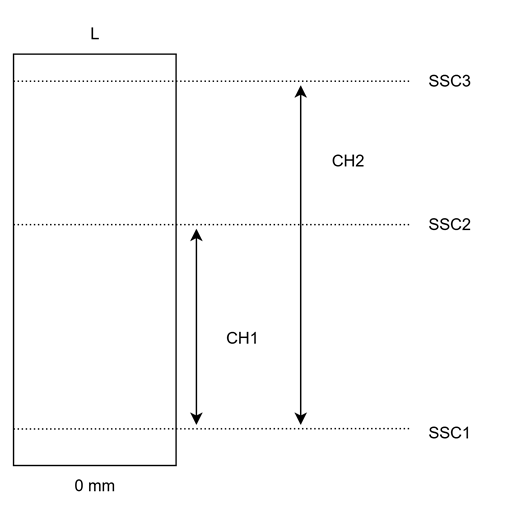
L: nominal length of the BTLCHx: stroke channelsSSCx: switching points
Distance counter
Description
The distance counter records the distance taken by the first position magnet (forward and backward as well). The value is determined independently of the configuration of the stroke channels and is specified as an absolute value. The counter is updated periodically.
A jitter window is used to determine the smallest recorded movement, therefore the position magnet movement must be greater than the value of this window. The window size can be adapted to the application.
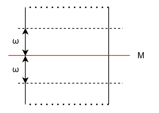
M: target position (first position magnet)ω: jitter window
The following distance counters are available:
All distance counter values are represented in μm.
Note
The Actual distance can be reset by the Reset distance system command, while the Since reset counter is reset by a Maintenance reset.
It is not possible to reset Lifetime distance.
Note
The Lifetime distance counter can be read out via SSI additional data (Movement distance).
Stroke counter
Description
The stroke counter counts the strokes performed for each activated stroke channel depending on the selected mode. The following counters are available for each channel:
Stroke counter |
Meaning |
|---|---|
Actual value |
Value since the last sensor start |
Since reset |
Value since the last maintenance reset |
Lifetime |
Value since the sensor was delivered |
Note
Only completed strokes are counted. Depending on the CHx stroke mode parameter the meaning of a complete stroke can vary, please refer to the stroke mode description.
Stroke deviation
Description
The stroke deviation feature constantly monitores the position deviation from the switching points assigned to a given channel. If the target position is within the CHx sensing window, the current deviation value is determined.
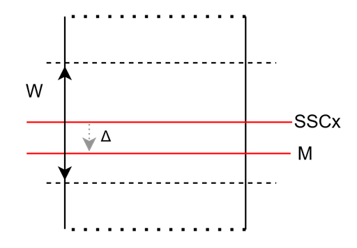
SSCx: switching pointM: target position (first position magnet)W: sensing windowΔ: deviation
For a given channel the Actual deviation value is in μm and it is a signed value. The other deviation values are statistical (relative) values expressed in percentage, refering to the channel’s stroke length in μm.
Note
Because the statistical deviation values are referring to the channel’s stroke length for longer stroke lengths these values will be effectively zero. These values mostly usefull for applications requiring short stroke lengths.
ISDU
Stroke monitoring configuration
CHx start
Switching signal channel index which marks the stroke channel’s start position. Multiple stroke channels can use the same switching signal channel.
SSC |
Value |
|---|---|
SSC1.1 |
0x00 (0) |
SSC1.2 |
0x01 (1) |
SSC1.3 |
0x02 (2) |
SSC1.4 |
0x03 (3) |
CHx end
Switching signal channel index which marks the stroke channel’s end position. Multiple stroke channels can use the same switching signal channel.
SSC |
Value |
|---|---|
SSC1.1 |
0x00 (0) |
SSC1.2 |
0x01 (1) |
SSC1.3 |
0x02 (2) |
SSC1.4 |
0x03 (3) |
CHx sensing window
The sensing window marks a symmetrical interval around a channel’s switching point, where the stroke deviation is determined. The window size must be between 100 μm and 100.000 μm (10 cm), including the limits.
CHx stroke mode
Defines the stroke mode for the given channel. The available stroke modes are the following:
Value |
Meaning |
|---|---|
0x00 (0) |
Single way |
0x01 (1) |
Single way - reverse |
0x02 (2) |
Double way |
0x03 (3) |
Double way - reverse |
CHx enable
Enables or disables a specific stroke channel.
Global enable
Enables or disables the stroke monitoring feature in general.
Data storage cycle
The counter values are periodically stored into non-volatile memory of the sensor. This cycle can be configured here. The cycle time must be between 60 and 3600 seconds, including the limits. The parameter is in seconds.
Jitter window
A jitter window is used to determine the smallest recorded movement. Shorter movements than the jitter window size are not recorded. The parameter is in μm and must be between 10 μm adnd 50.000 μm, including the limits.
Note
Setting the Jitter window to the minimum can have the risk that increased noise in the position can be recorded as movement.
Distance counter
Actual distance
Distance travelled by the first position magnet since the sensor is powered or since the last Distance reset command. The value is in μm.
Since startup
Distance travelled by the first position magnet since the sensor is powered. The value is in μm.
Since reset
Distance travelled by the first position magnet since the last Maintenance reset is executed. The value is in μm.
Lifetime
Total distance travelled by the first position magnet since delivery. This value cannot be reset. The value is in μm.
Stroke counter
CHx actual
Shows the current stroke count since the sensor startup.
CHx since reset
Shows the stroke count since the last Maintenance reset.
CHx lifetime
Shows the total number of strokes on a given channel since the sensor was shipped. This value cannot be reset.
Stroke deviation
CHx actual
If the target is currently in the sensing window around the switching point, then it shows the current deviation in μm. If the target is outside of the sensing window, then it shows the minimum recorded deviation in μm.
CHx startup relative
Shows the stroke deviation of a given channel since the sensor startup in percentage of the channel’s stroke length.
CHx reset relative
Shows the stroke deviation of a given channel since the last Maintenance reset in percentage of the channel’s stroke length.
CHx lifetime relative
Shows the stroke deviation of a given channel since it was shipped in percentage of the channel’s stroke length. This value cannot be reset.