SmartLight control
Description
Using the SmartLight control feature, the following operations can be performed:
Selection of the main LED functionality (segment inmodedicator, level mode, etc.)
Adjustment of the brightness of the main LEDs
Configuration of customer specific colors
Advanced digital IO mode configuration
Demo mode configuration
Safe state configuration
Status LED configuration
Synchronization
Adjustment of the brightness of the main LEDs
The brightness of the main LEDs are adjustable as a global brightness functionality. All of the LEDs will be affected by this brightness. It is implemented as a two stage brightness modification.
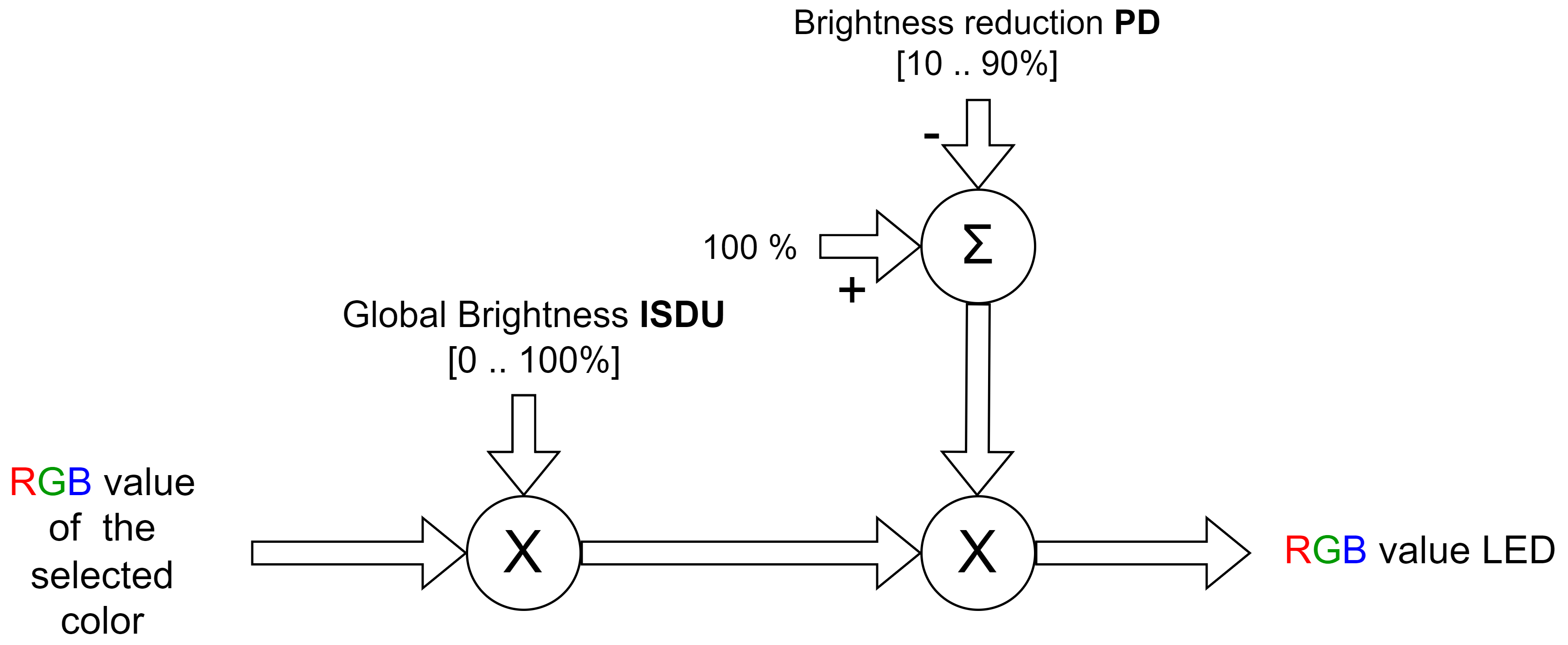
The RGB value defined by the current color will be weighted by the brightness ISDU in the first stage. The intended use of the Brightness ISDU is setting the brightness once, in case the default value is not proper for the current application. There is a second stage for the brightness correction, which is called brightness reduction. This can be done via process data. The intended use of this brightness value is reducing the brightness temporary. With the temporary reduction the brightness can be reduced for example during the night shift.
Configuration of customer specific colors
The SmartLight has 8 pre-definied colors. It is possible to configure 7 additional colors as a user defined color.
Advanced IO mode configuration
The SmartLight can operate in advanced IO mode (SIO mode) where no IO-Link is available. There are default values configured for the SIO mode, but the user has the capability to overwrite them to have a customer specific SIO functionlaity. The desired signal functionality can be set via ISDU, or can be teached-in with a system command.
Demo mode configuration
Demo mode can be activated and deactivated with a system comment, to see the rich functionality of the device. It is intended to use for demo purpose. The demo sequence type can be selected from some pre-defined sequences.
Safe state configuration
In case of communication loss, the SmartLight will signalize the so called safe state condition. The upper LEDs will blink in red to signalize the lost of communication, when the safe-state signal is enabled.
Status LED configuration
The brightness of the status LED is configurable.
Output process data bitfield descriptions
Mode selection
The main LEDs can realize differnet indicators:
Segment mode
Level mode
Runlight mode
Flexible mode
Ultimate mode The process data will be interpredet different, depending on the selected indicator mode.
Value |
Description |
|---|---|
0 |
Forced OFF mode |
1 |
|
2 |
|
3 |
|
4 |
|
5 |
Sync start
When a rising edge is detected on the Sync start bit, the SmartLight resets its internal state. This assures that the syncronised SmartLights start to work in the same state. The Sync start rising edge has to be generated once after a reset.
Sync impulse
When a rising edge is detected on the Sync impulse bit, the SmartLight resets its internal timer. It has to be generated cyclically in order to keep the SmartLights synchronised. The time period of the Sync impluse can be configured by the user. It´s recommended to set the values between 1 sec. and 15 sec., depending on the frequency of the synchronised parameters.
Brightness reduction
The global brightness of the main signal LEDs can be changed via ISDU and process data. The conbination of the two settings will result the brightness of the main signal LEDs.
Value |
Description |
|---|---|
0 |
No reduction |
1…9 |
Reduction by 10% … 90% |
11…15 |
Reduce by 90% |
ISDU
Name |
Index |
Subindex |
Access |
Length |
Data Type |
DataStorage |
Default |
|---|---|---|---|---|---|---|---|
Global Brightness |
0x01B3 (435) |
0 |
R/W |
1 bte |
UINT8 |
Yes |
100 |
Safe State |
0x01B4 (436) |
0 |
R/W |
1 byte |
BOOL |
Yes |
false |
User Color 1 |
0x01B5 (437) |
0 |
R/W |
4 bytes |
UINT32 |
Yes |
0x00FF7F00 |
User Color 2 |
0x01B6 (438) |
0 |
R/W |
4 bytes |
UINT32 |
Yes |
0x007FFF00 |
User Color 3 |
0x01B7 (439) |
0 |
R/W |
4 bytes |
UINT32 |
Yes |
0x00000FF7F |
User Color 4 |
0x01B8 (440) |
0 |
R/W |
4 bytes |
UINT32 |
Yes |
0x00007FFF |
User Color 5 |
0x01B9 (441) |
0 |
R/W |
4 bytes |
UINT32 |
Yes |
0x007F00FF |
User Color 6 |
0x01BA (442) |
0 |
R/W |
4 bytes |
UINT32 |
Yes |
0x00FF007F |
User Color 7 |
0x01BB (443) |
0 |
R/W |
4 bytes |
UINT32 |
Yes |
0x007F7F7F |
Advanced Digital - 000 |
0x0215 (533) |
0 |
R/W |
ARRAYT |
Yes |
||
Advanced Digital - 001 |
0x0216 (534) |
0 |
R/W |
ARRAYT |
Yes |
||
Advanced Digital - 010 |
0x0217 (535) |
0 |
R/W |
ARRAYT |
Yes |
||
Advanced Digital - 011 |
0x0218 (536) |
0 |
R/W |
ARRAYT |
Yes |
||
Advanced Digital - 100 |
0x0219 (537) |
0 |
R/W |
ARRAYT |
Yes |
||
Advanced Digital - 101 |
0x021A (538) |
0 |
R/W |
ARRAYT |
Yes |
||
Advanced Digital - 110 |
0x021B (539) |
0 |
R/W |
ARRAYT |
Yes |
||
Advanced Digital - 111 |
0x021C (540) |
0 |
R/W |
ARRAYT |
Yes |
||
Status LED Brightness |
0x01BC (444) |
0 |
R/W |
1 byte |
UINT8 (ENUM) |
Yes |
2 |
Demo Pattern Selector |
0x01CD (461) |
0 |
R/W |
1 byte |
UINT8 (ENUM) |
Yes |
0 |
Global Brightness
The global brightness can be set as a percent value. Values from 0 to 100 are allowed.
Safe State
Value |
Meaning |
Description |
|---|---|---|
0x0 (0) |
Disabled |
All of the LEDs will be switched on in case of communication lost. |
0x1 (1) |
Enabled |
Safe-state signel will be signalized in case of communication lost. |
User Color X
The RGB code of the user defined color can be set. Each color component can have an 8 bit value.
Bits |
Meaning |
|---|---|
0…7 |
8 bit value for component blue |
8…15 |
8 bit value for component green |
16…23 |
8 bit value for component red |
23…31 |
Reserved |
Advanced Digital - XYZ
The state of the SmartLight (main LEDs, buzzer, and strobe light) is determined at all times by the current process data and the ISDU content. In advanced digital I/O mode, no IO-Link communication is active, therefore no process data is available. The ISDU values are still available in the device, as they are stored internally. To define the state of the SmartLight for each advanced digital I/O mode combination, a simulated process data value is stored in the corresponding ISDU. This allows the device, despite not receiving any actual process data, to use the stored value as if it were provided by the IO-Link master, ensuring that the SmartLight state is fully defined.
BNI IOL-811-205-K03x, BNI IOL-812-205-K03x, default configurations
The SmartLight is configured for Segment indicator, with 3 segments.
Input combination |
Segment 1 |
Segment 2 |
Segment 3 |
|---|---|---|---|
000 |
off |
off |
off |
001 |
off |
off |
red |
010 |
off |
yellow |
off |
011 |
off |
yellow |
red |
100 |
green |
off |
off |
101 |
green |
off |
red |
110 |
green |
yellow |
off |
111 |
green |
yellow |
red |
BNI IOL-810-205-K03x, default configurations
Input combination |
Segment 1 |
Strobelight |
|---|---|---|
000 |
off |
off |
001 |
red |
off |
010 |
yellow |
off |
011 |
green |
off |
100 |
off |
on |
101 |
red |
on |
110 |
yellow |
on |
111 |
green |
on |
Status LED Brightness
Value |
Meaning |
|---|---|
0x00 |
Off |
0x01 |
Low |
0x02 |
Medium |
0x03 |
High |
Demo Pattern Selector
Differnet patterns can be set as a demo mode.
Value |
Demo pattern |
|---|---|
0x00 |
Default demo sequence showing the rich functinality of the SmartLight |
0x01 |
Lava lamp, color red and yellow |
0x02 |
Lava lamp, color magenta and cyan |
0x03 |
Lava lamp, color blue and magenta |
0x04…0x08 |
The same pattern as in case 0x00 |
System Commands
Command Value |
Device Action |
|---|---|
0x81 (129) |
Application Reset – Reset ISDUs of SmartLight control functionality to the default value. |
0x82 (130) |
Restore Factory Settings – Reset ISDUs of SmartLight control functionality to the default value. |
0xD0 (208) |
Deactivate demo mode |
0xD1 (209) |
Activate demo mode |
0xC2 (194) |
Teach current PD for advanced IO mode, input combination 000 |
0xC3 (195) |
Teach current PD for advanced IO mode, input combination 001 |
0xC4 (196) |
Teach current PD for advanced IO mode, input combination 010 |
0xC5 (197) |
Teach current PD for advanced IO mode, input combination 011 |
0xC6 (198) |
Teach current PD for advanced IO mode, input combination 100 |
0xC7 (199) |
Teach current PD for advanced IO mode, input combination 101 |
0xC8 (200) |
Teach current PD for advanced IO mode, input combination 110 |
0xC9 (201) |
Teach current PD for advanced IO mode, input combination 111 |
For an overview of all System Commands, see section System Commands.