Product description
Overview
The SmartLight is a configurable visual and acoustic signaling device designed to communicate machine states, process conditions, and operator notifications. Depending on the product configuration, various signaling functions are available.
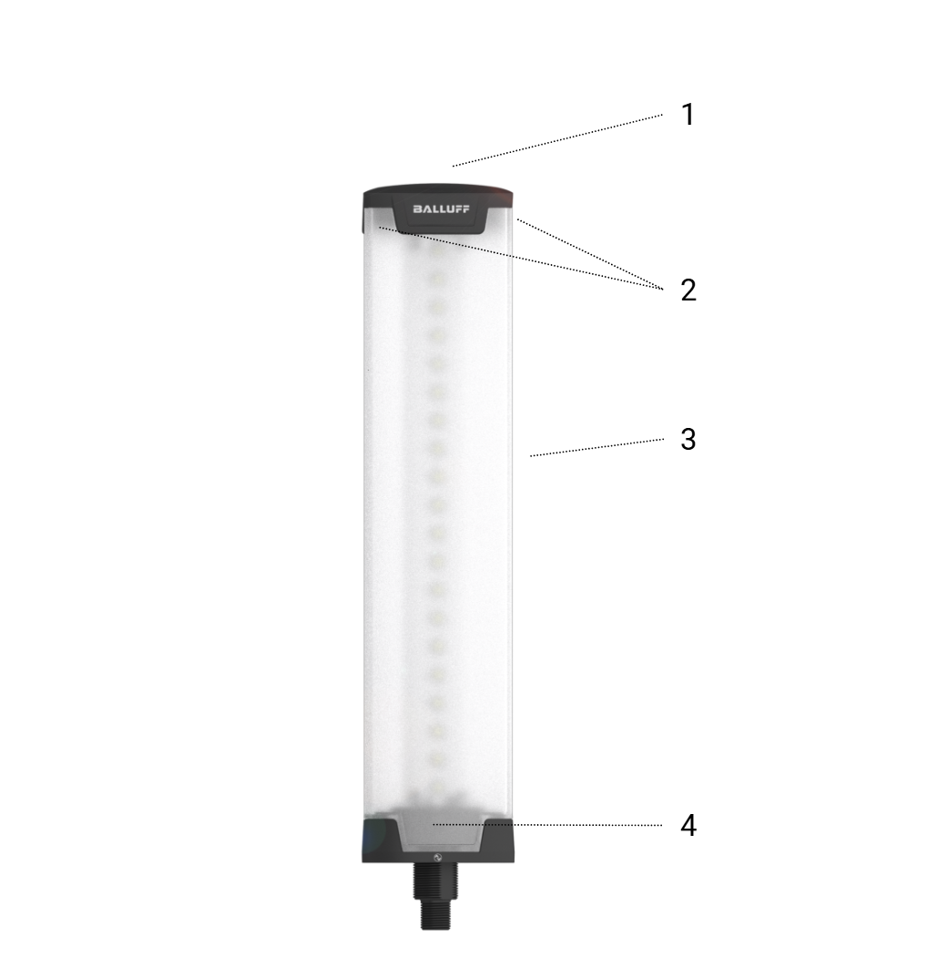
1 |
Buzzer (optional) |
2 |
StrobeLight (optional) |
3 |
Main LEDs (4, 12 or 20 per side) |
4 |
Status LED |
Note
The buzzer and strobe light functions are only available on product variants equipped with the optional buzzer/strobe light module.
The presence of this module can be identified from the type code. If the last block of the type code contains K037, the product includes the buzzer/strobe light module. If K036 is present, these functions are not available.
Status Light States
Display |
Meaning |
Green, static |
Device is ok, no IO-Link |
Green, blinking, ratio 10:1, 1Hz |
Device is ok, IO-Link active |
Blue, static |
Maintenance required |
Blue, blinking 3Hz |
Device Discovery to find the device among others (Ping) |
Yellow, blinking 3Hz |
Device operates out of specification |
Red, static |
General error |
Main Light States
Display |
Meaning |
Blue, blinking 3Hz |
Device Discovery to find the device among others (Ping) |
Function
This chapter is an overview of the included functionality of the product. For detailed information about the available functions, configuration options, and programming methods, refer to Section Software Functions and Setup.
Main Signal Functions
Main Signal LED
The main signal LED is used to visualize machine states, process information, warnings, and status indications. Various operating modes, colors, and signal patterns can be configured to suit the application requirements.
Buzzer
The integrated buzzer provides acoustic signaling for warnings, alarms, and status notifications. Acoustic signals can be used either independently or in combination with visual signals.
Strobe Light
The strobe light provides a highly visible flashing signal to attract attention in environments where standard visual signals may not be sufficiently noticeable or where acoustic warnings may be ineffective due to ambient noise.
Additional Functions
Demo Mode
The demo mode provides a predefined sequence of visual and acoustic signals to demonstrate the capabilities and functionality of the device. This mode is intended for demonstration and evaluation purposes only.
Synchronization
Synchronization mode allows multiple SmartLight devices to operate with aligned timing and signal transitions. This ensures a consistent visual appearance across all synchronized devices.
Compatibility Mode
Compatibility mode allows the device to emulate a SmartLight of the previous Silver Line generation. In this mode, the corresponding legacy IODD is supported, enabling existing PLC programs and engineering configurations to continue operating without modification.
Extended Mode
Extended mode enables the operation of two SmartLight devices on a single IO-Link port by using a compatible splitter cable. Both devices remain individually controllable. Functional limitations and application-specific restrictions apply.
Main Signal Functions
The main signal LEDs support multiple operating modes to visualize machine states, process information, warnings, and status indications.
Segment Indicator
The Segment Indicator represents the traditional signal tower functionality by assigning individual signal states to dedicated LED segments.
To increase flexibility, the SmartLight supports an automatic scaling function (Auto Scale). In this mode, the device automatically adapts the displayed segments to the number of active signals without requiring a fixed segment count to be configured in advance.
Applications requiring a predefined segment arrangement can use a fixed segment configuration. The available number of segments depends on the product variant. For further details, refer to Section segment-count.
Level Indicator
The Level Indicator is designed for applications where progress, filling levels, utilization, or similar continuously changing values need to be displayed.
The displayed level can be shown with or without a background color. Additionally, the displayed color can change automatically based on configurable threshold values. For example, the indicator can transition from green to yellow and finally red as defined limits are reached.
Runlight Indicator
The Runlight Indicator displays a continuously moving light segment across the signal area.
The running light can be configured with or without an illuminated background and is particularly suitable for applications requiring enhanced visibility of warning or operating states.
Flexible Configurable Indicator (Flexible Mode)
Flexible Mode provides the same functionality as the Flexible Mode available in the Silver Line SmartLight generation.
In this operating mode, the LED states are controlled via process data, while colors and configuration parameters are assigned through acyclic communication (ISDU). This separation allows dynamic control of signal states while maintaining flexible color configuration.
Highly Flexible Configurable Indicator (Ultimate Mode)
Ultimate Mode extends the capabilities of Flexible Mode by allowing nearly all signaling parameters to be controlled directly through process data.
In addition to LED activation states, parameters such as colors, brightness settings, and selected animation effects can be dynamically controlled during operation without requiring acyclic parameter access.
Ultimate Mode is is not supported for the BNI IOL-812-205-K03x in Extended Mode, where two SmartLight devices share a single IO-Link port.
Size of the main signal area
Device Variant |
Number of LED levels |
|---|---|
BNI IOL-810-205-K03x |
4 |
BNI IOL-811-205-K03x |
12 |
BNI IOL-812-205-K03x |
20 |
Note
The SmartLight has LEDs above each other (if SmartLight mounted vertically). The term LED level will be used in this manual, which means three LEDs (one on each side of the SmartLight) in the same vertical position.
Operation Modes
The product communicates with the higher-level controller via the IO-Link interface. Depending on the application requirements, the interface can be operated in one of three different modes:
Single Mode (default):
Standard operating mode for direct connection to an IO-Link master using a conventional IO-Link cable.
Extended Mode:
Allows two identical SmartLight devices to be connected individually via a splitter cable to a single IO-Link master port, reducing the number of required master ports.
Advanced Digital I/O Mode (SIO Mode):
Enables operation as a digital I/O device without IO-Link communication. In this mode, the product can be controlled exclusively via the digital input signals.
Single mode
Single Mode is the standard IO-Link operating mode of the SmartLight. In this mode, one SmartLight is connected to a single IO-Link master port and operates independently as an individual signal indicator.
All process data, parameters, diagnostic information, and device settings are exchanged via the IO-Link communication channel. This enables full access to all SmartLight functions, including configuration, status monitoring, and control from the higher-level PLC or controller.
The product is delivered with Single Mode configured as the factory default setting. For most applications, no additional configuration is required and the device can be connected directly to a standard IO-Link master using a conventional IO-Link cable.
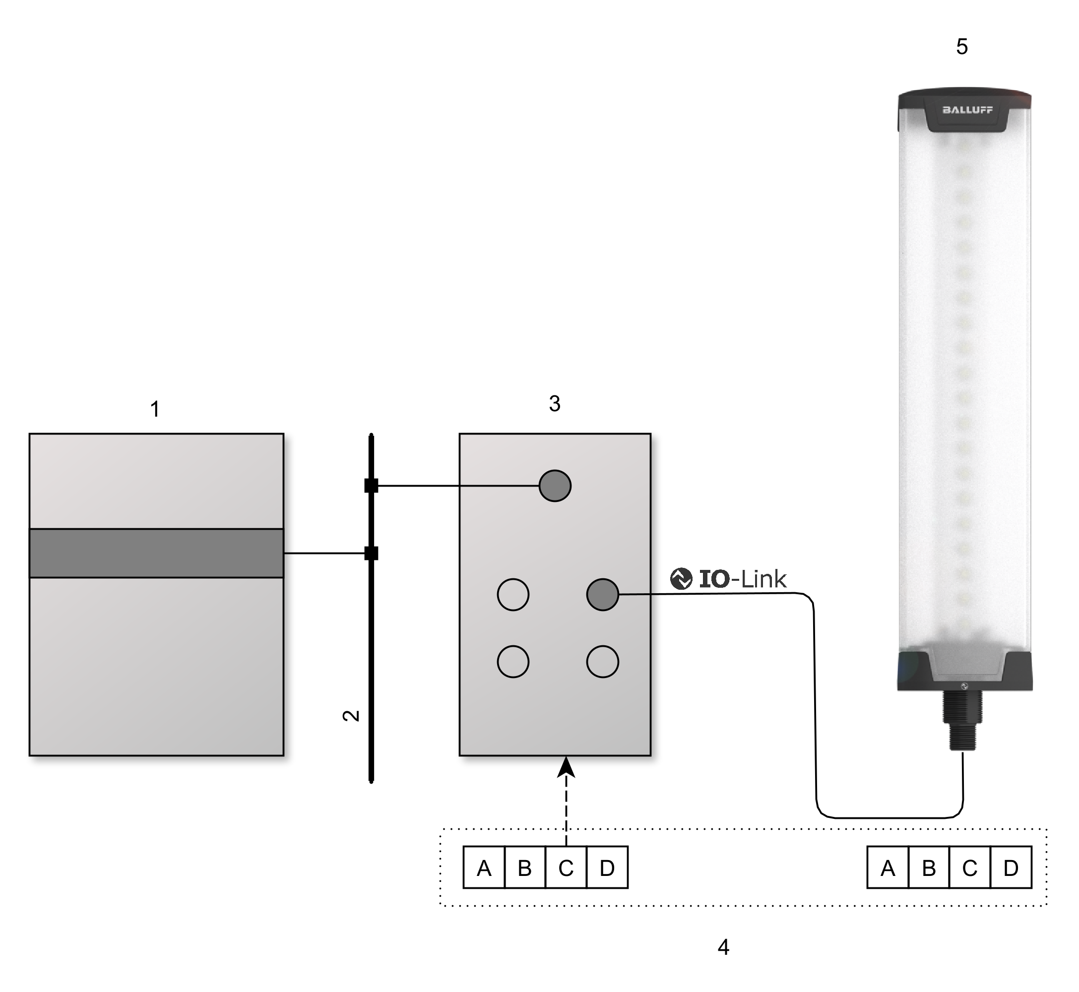
1 |
PLC |
2 |
field bus |
3 |
IO-Link master |
4 |
Process data or ISDU data |
5 |
SmartLight configured to single mode. |
Extended mode
Extended Mode allows two identical SmartLight devices to be operated independently on a single IO-Link master port. In this configuration, one device acts as the primary device connected directly to the IO-Link master, while the second device is connected via the integrated extension interface. As a result, both devices can be controlled individually without requiring an additional IO-Link master port.
Communication with the higher-level controller is still performed through a single IO-Link connection. The process data exchanged via IO-Link contains the information and control data for both connected SmartLight devices, enabling independent operation and configuration of each signal indicator.
Extended Mode is particularly useful in applications where multiple SmartLights are required but the number of available IO-Link master ports is limited. By operating two devices on a single master port, wiring complexity and system costs can be reduced while maintaining the functionality of two independent signaling devices.
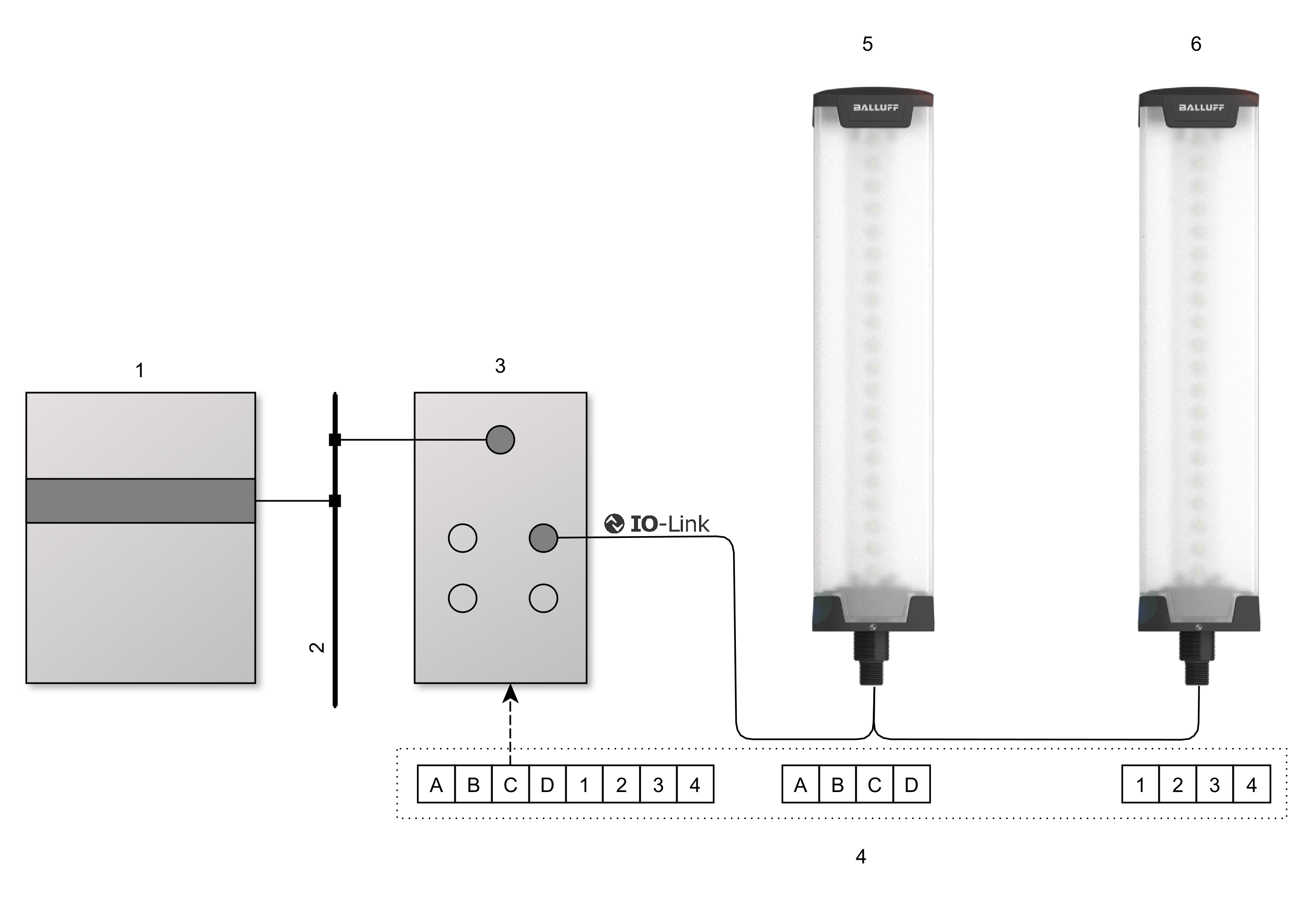
1 |
PLC |
2 |
field bus |
3 |
IO-Link master |
4 |
Process data or ISDU data |
5 |
Primary device (SmartLight configured to extended mode) |
6 |
Secondary device (SmartLight configured to single mode) |
Note
For extended mode special cable accessories are available in various length:
BCC0K6M
BCC0K6R
BCC0K6N
BCC0K6P
Advanced digital IO mode (SIO mode)
Advanced Digital I/O Mode (SIO Mode) allows the SmartLight to be operated without an active IO-Link connection during normal operation. In this mode, the device functions as a standalone signal indicator and is controlled exclusively through its digital inputs.
Prior to operation, the SmartLight is configured via IO-Link using an engineering tool. During this configuration step, the desired signaling behavior is assigned to each possible combination of the three available digital inputs. For every input state, individual light effects, colors, flashing patterns, and buzzer functions can be defined according to the application requirements.
Once the configuration has been completed, IO-Link communication is no longer required. During operation, the SmartLight continuously monitors the state of its three digital inputs and activates the corresponding signaling pattern based on the configured input combination.
SIO Mode is particularly useful for retrofitting existing or legacy machines that do not support IO-Link communication. It enables the SmartLight to provide advanced visual and acoustic signaling functions while being integrated into conventional digital I/O control architectures.
Note
Open wires are not permitted when operating the product in SIO/Digital Mode.
Unconnected wires create undefined signal levels that may lead to incorrect input state detection. As a result, unintended operation or unexpected output signals may occur.
To ensure reliable operation, all input pins shall be connected to a defined potential (HIGH or LOW ) and shall not be left floating.
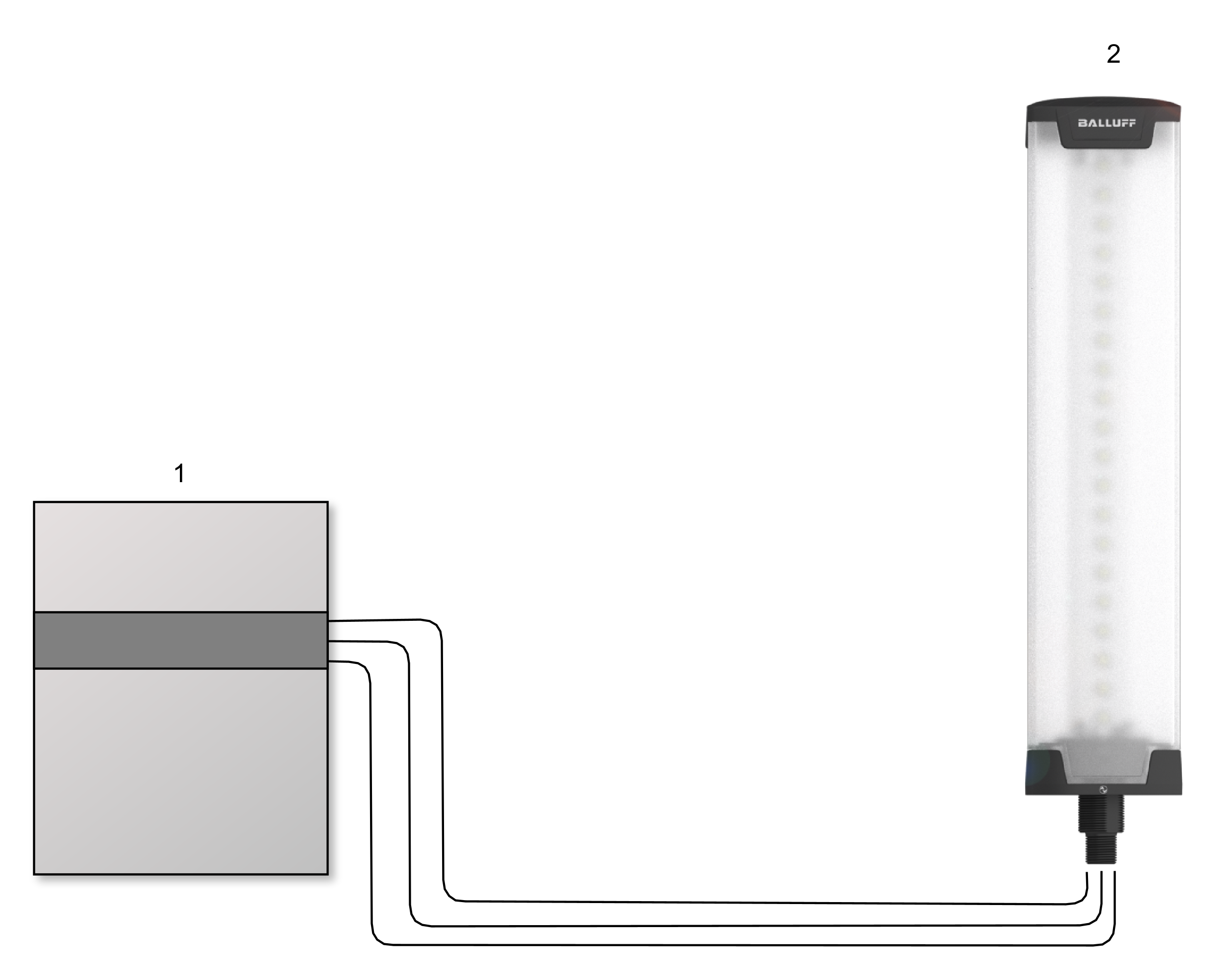
1 |
PLC |
2 |
SmartLight configured to SIO mode |