Imaging Configuration (taskImaging)#
taskImaging#
The imaging section contains parameters that select the relevant recorded data to generate an image (stack).
- Use
layerSelection.indexesto choose the layer(s) (z-distance) to display. - Use
transposeandflipto adjust image orientation. - Use
normalAbs(and optionallogScale) to normalize and scale the data into an 8-bit image.
layerSelection.indexes#
Selects the layer(s) of the recorded data to display in the image. The layer index corresponds to a specific distance from the RadarImager (z-axis).
- Layer index
0corresponds to 100 mm distance (layers closer than 100 mm are not selectable). - The distance between two selectable layers is 2.726 mm.
To compute the layer distance:
layerDistance = 100 mm + layerIndex × 2.726 mm
Dependency
The maximum selectable layer index is limited by the measurement parameter
distanceZToDeepestLayerOfInterest.
The layer distance must not exceed this configured depth.
| Property | Value |
|---|---|
| type | IntVector |
| Values (default) | 0 |
| minInclusive | 0 |
| maxExclusive | 147 |
Change layerSelection.indexes to find the layer of interest:
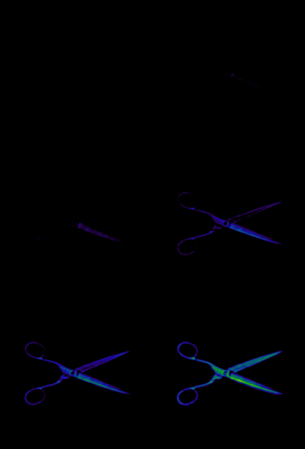
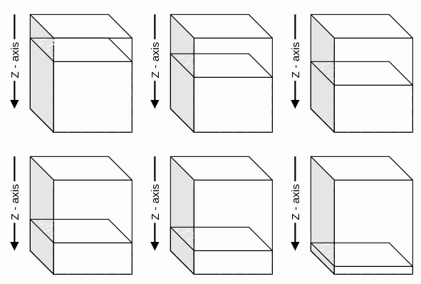
The normalAbs.kind value GLOBAL can help to find the object more easily.
GenDC
- If single-image mode is enabled and multiple layers should be transferred, list the desired layer indexes separated by commas.
- The first layer starts at
0. - Be aware of the GenDC limitations in GenDC limitations.
Example
- To receive layers 0, 1 and 2, use:
0,1,2 - To receive layers 2, 5, 10 and 11, use:
2,5,10,11
flip.dim_1#
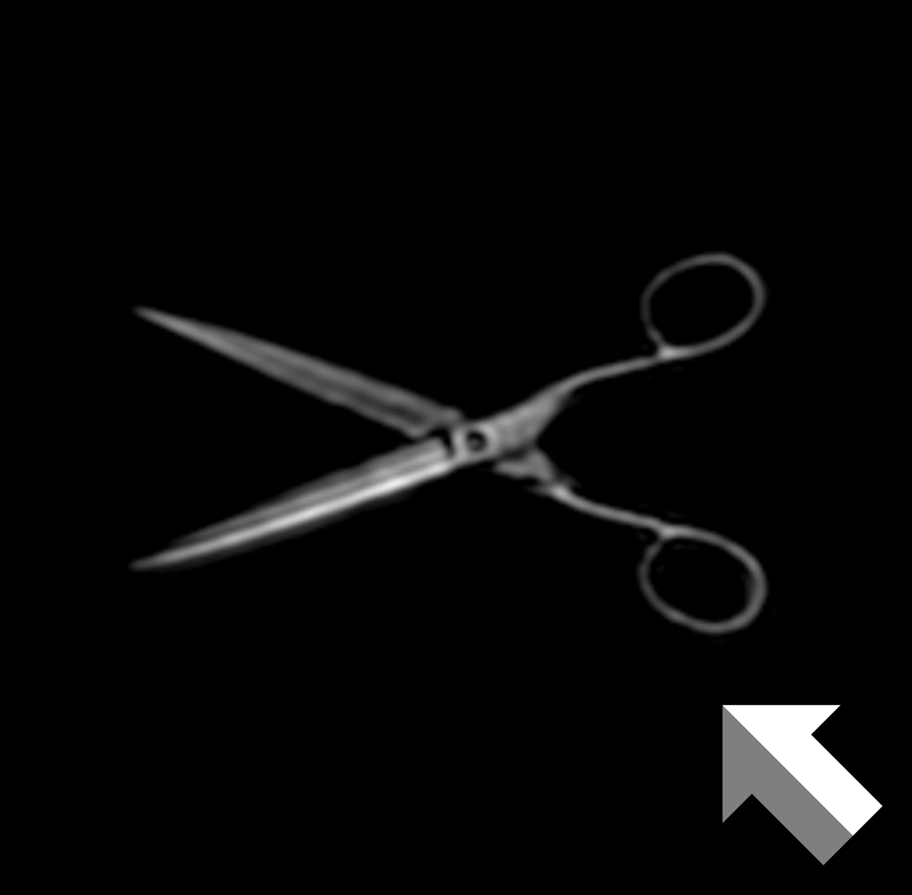
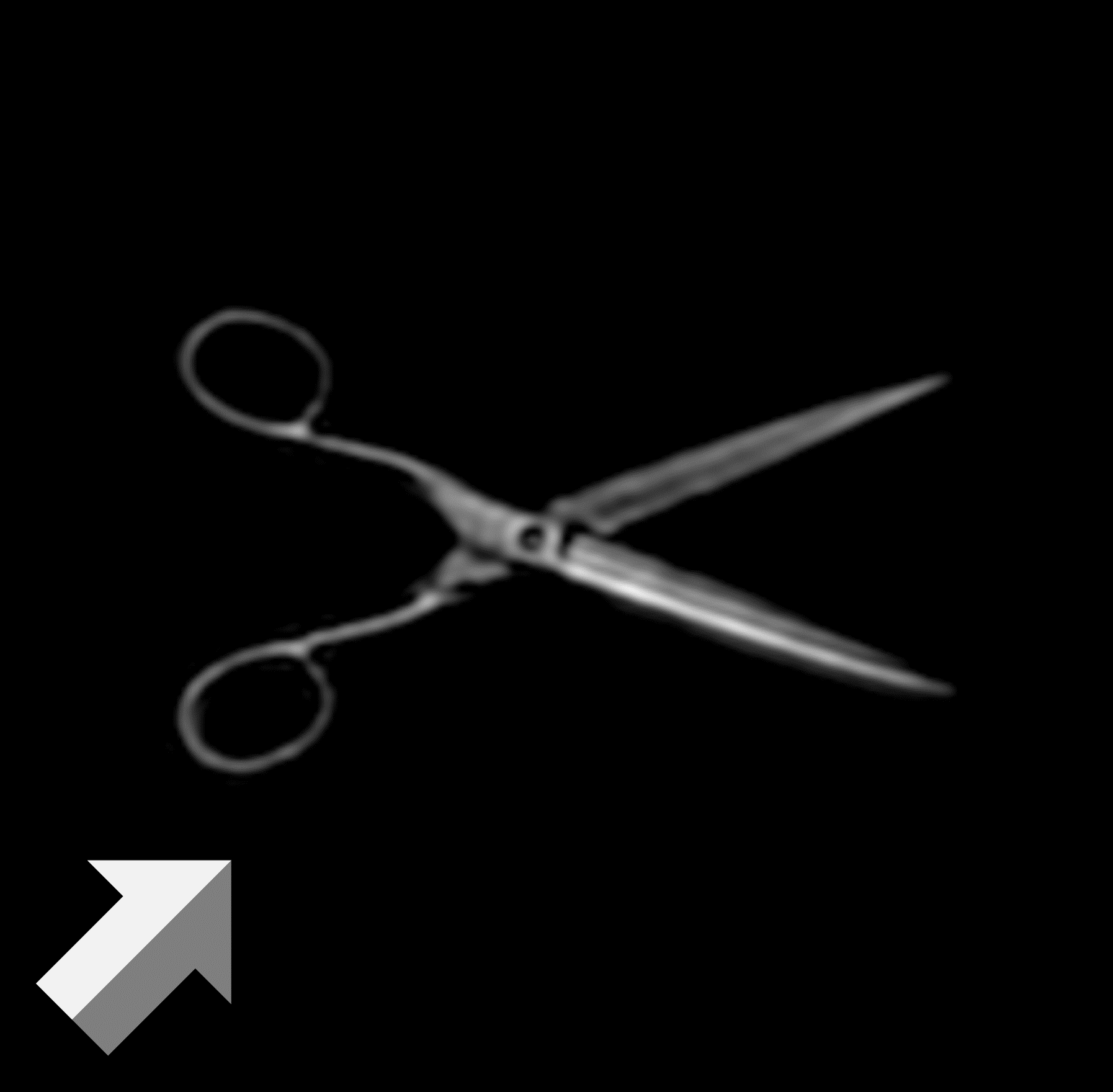
Mirrors the image along the direction of motion (x-axis).
| Property | Value |
|---|---|
| type | Option |
| Flag (default) | false |
flip.dim_2#
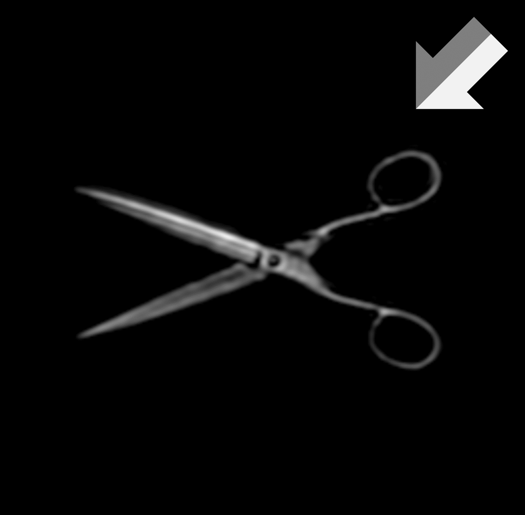
Mirrors the image along the antenna direction (y-axis).
| Property | Value |
|---|---|
| type | Option |
| Flag (default) | false |
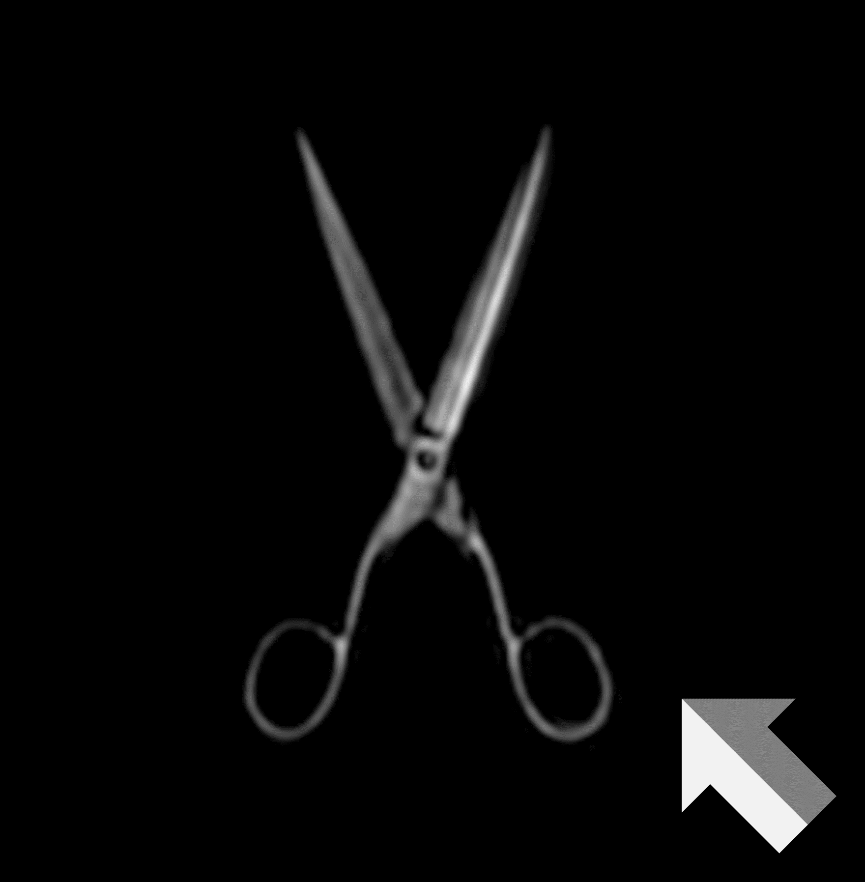
transpose#
Swaps the x- and y-dimensions of the image.
Default
By default, the movement direction (x-axis) is shown horizontally and the antenna direction (y-axis) vertically.
| Property | Value |
|---|---|
| type | Option |
| Flag (default) | false |
channelSelection.conversion#
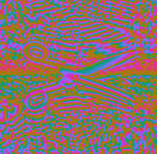
Selects which data is used to generate the image:
ABS: absolute valuesPHASE: phase informationABS_PHASE: phase image with brightness weighted by ABS values (seecoloring)
| Property | Value |
|---|---|
| type | Enum |
| Value (default) | ABS |
| elements | [ABS, PHASE, ABS_PHASE] |
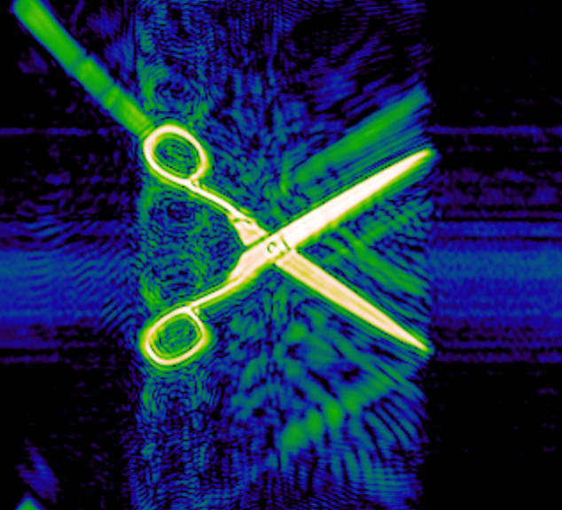
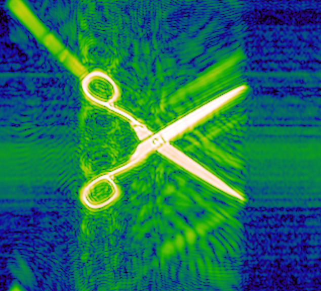
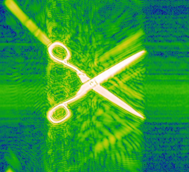
channelSelection.conversion examples: ABS (left), PHASE (middle), ABS_PHASE (right):


Learn more
Learn more about abs and phase information and its use cases in Image Data & Interpretation.
normalAbs#
Parameters of this node define how captured data is normalized and scaled to generate the image. The data is normalized into an 8-bit integer range for efficiency and compatibility with standard image formats. Depending on the application, scaling can be adjusted to highlight specific features.
Note
These parameters are only relevant for images that contain ABS information, because PHASE information is always normalized in the range of 2π.
normalAbs.kind#
Determines how image data is normalized:
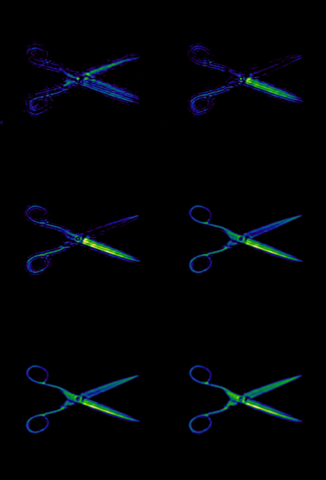
LAYER: normalizes each layer individually (dynamic per measurement).GLOBAL: normalizes all layers equally (still dynamic per measurement). The available layers depend ondistanceZToDeepestLayerOfInterest.PREDEFINED: normalizes all layers equally using fixed min/max configured byminPredefinedValandmaxPredefinedVal.
| Property | Value |
|---|---|
| type | Enum |
| Value (default) | LAYER |
| elements | [LAYER, GLOBAL, PREDEFINED] |
Use the LAYER normalization kind to get a guaranteed visual representation of each layer.
This normalization kind is useful to get an impression of the layer and its specific features.
The GLOBAL normalization kind is useful to compare layers to identify those with particularly high reflection factors.
Depending on the application, this is very often close to the layer of interest, and can therefore be used to find it quicker.
Examples for normalAbs.kind: LAYER (left) compared to GLOBAL (right) while navigating layers:
Tip
Reload the page or press F5 to make sure the GIFs run simultaneously.
PREDEFINED should be used in production environments or when image data is used for further processing.
It keeps normalization stable across measurements.
For details, see Image Data Normalization.
normalAbs.minPredefinedVal#
Defines the minimum value for the PREDEFINED normalization kind.
Dependency
Only relevant if normalAbs.kind is PREDEFINED.
| Property | Value |
|---|---|
| type | Real |
| Value (default) | 0 |
| unit | % |
| minInclusive | 0 |
| maxInclusive | 100 |
See the example in normalAbs.maxPredefinedVal.
normalAbs.maxPredefinedVal#
Defines the maximum value for the PREDEFINED normalization kind.
Dependency
Only relevant if normalAbs.kind is PREDEFINED.
Constraint
maxPredefinedVal must be greater than minPredefinedVal,
otherwise the image will not contain any information.
| Property | Value |
|---|---|
| type | Real |
| Value (default) | 100 |
| unit | % |
| minInclusive | 0 |
| maxInclusive | 100 |
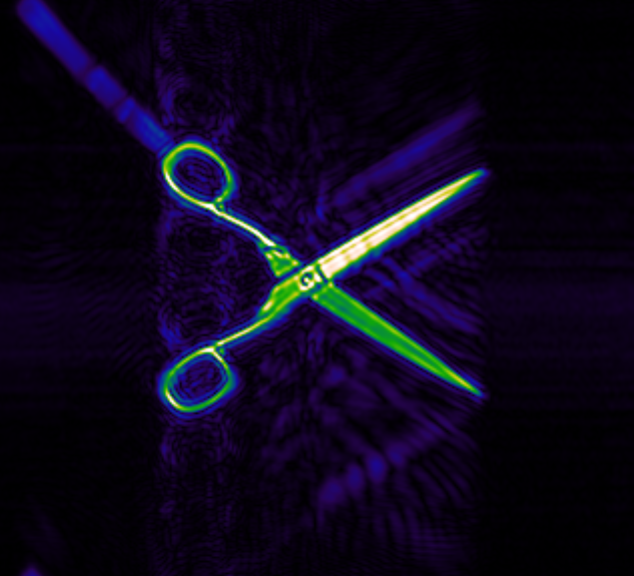
Example: reducing maxPredefinedVal 100% → 41% (left → middle) and increasing minPredefinedVal 0% → 20% (middle → right)
expands the visible dynamic range for the scissors:


For more details and examples, see Image Data Normalization.
normalAbs.logScale#
Enables logarithmic compression of ABS data.
The effective dynamic range is controlled by normalAbs.dynamics.
Dependency
Only available for data containing ABS values as configured by channelSelection.conversion.
| Property | Value |
|---|---|
| type | Option |
| Flag (default) | false |
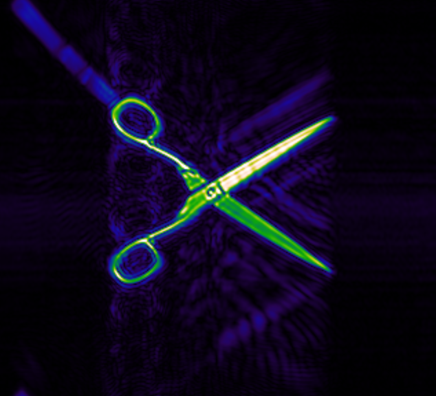
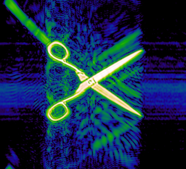
Example with normalAbs.dynamics = 20 dB (left: disabled, right: enabled):
normalAbs.dynamics#
Controls the strength of logarithmic compression and therefore how values are mapped by magnitude.
Dependency
Only relevant if normalAbs.logScale is enabled.
| Property | Value |
|---|---|
| type | Real |
| Value (default) | 20 |
| unit | dB |
| minInclusive | 0.01 |
| maxInclusive | 390 |
Smaller dynamics values increase contrast for weak signals but may suppress low values more aggressively.
Larger values compress more strongly.
Note: Smaller dynamics values may clip or suppress lower input values more aggressively, effectively reducing sensitivity to quiet or weak signals. The unit for this parameter can be interpreted as a dynamic range in dB.
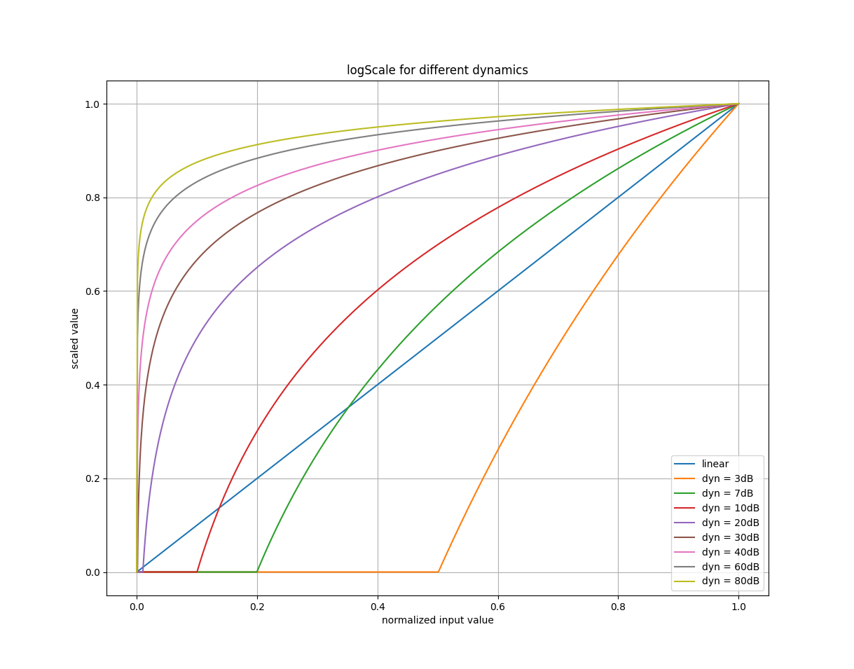
Example for different dynamics values: (5 dB, 10 dB, 20 dB, 30 dB, and 40 dB)