RadarImager Connectors and Indicators#
Connector and Indicators overview#
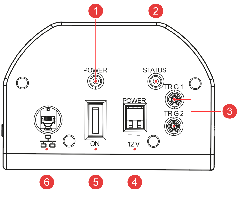
| Pos. | Description |
|---|---|
| 1 | Power-LED 🔵 |
| 2 | Status-LED 🟡 |
| 3 | Trigger input(s): Input for trigger sensor 1 (object detection and image generation). Optional trigger 2 for object movement direction detection or live speed measurement with encoder. |
| 4 | Power supply connector — 12 V DC, 10 A |
| 5 | Power switch |
| 6 | Ethernet connector (RJ45) |
LED indicator overview#
Power LED 🔵#
| Status | Description |
|---|---|
| Off | No power supply connected, or power switch is set to off. |
| Blue | RadarImager is powered. |
Status LED 🟡#
| Status | Description |
|---|---|
| Off | System is booting. |
| Flashing (short on, long off) |
System initialization in progress. |
| Blinking | RadarImager is active and measuring continuously. |
| Fast blinking | Trigger event detected — device is recording data used for image generation. |
| Constantly on or off | Error condition. Consult the troubleshooting guide or contact support. |