Measurement & Trigger Configuration (taskMeasurement)#
taskMeasurement.measurement.radarSystem#
These parameters describe how the RadarImager turns continuous measurement data into a triggered image:
- The RadarImager continuously records measurement data while active.
- An image is generated when the configured trigger condition occurs (see
useExternalTriggerandimageTriggerMode).
When changes take effect
Most parameters update the displayed image immediately using the latest measurement data. Some measurement parameters only take effect after a new measurement (i.e. the object must pass the RadarImager again). See Update of the RadarImager configuration for background.
Installation geometry overview#
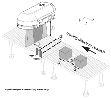
| Position | Description |
|---|---|
| 1 | Distance from the RadarImager to the deepest layer of interest in z-direction: distanceZToDeepestLayerOfInterest. |
| 2 | Distance between the trigger sensors. |
| 3 | Distance between the trigger reference line and the RadarImager system reference line: offsetDistanceX. |
| 4 | Output image length in movement direction x: objectLengthX. |
| 5 | Distance between consecutive target objects. |
The imageTriggerMode parameter defines whether one or two trigger sensors are used.
Trigger sensor spacing
The distance between the trigger sensors (Position 2) is currently not used to compute the image. However, the distance between consecutive objects (Position 5) must be greater than the sensor spacing so that two objects can’t be interpreted as one direction-sensitive trigger sequence.
In the graphic above, the objects move opposite to the default movement direction.
Therefore reverseObjectMovementDirectionX needs to be set to true.
objectSpeedX#
Sets the constant object speed along the movement direction (x-axis).
Higher speeds work well up to 1000 mm/s (1 m/s) without image quality loss. Changing this parameter by more than ~50% while images are being generated can cause an ongoing image generation to abort.
Dependency
If imageTriggerMode is IMAGE_TRIGGER_SIMPLE_WITH_PULSED_SPEED (live speed measurement via pulses on Trigger Port2),
objectSpeedX is ignored.
| Property | Value |
|---|---|
| type | Real |
| Value (default) | 200 |
| unit | mm/s |
| minInclusive | 5 |
| maxInclusive | 1000 |
objectLengthX#
Sets the object length along the movement direction (x-axis). This value determines the length of the generated image.
Applies after new measurement
Changing this parameter requires a new measurement (the object must pass again), because it changes the image dimensions.
| Property | Value |
|---|---|
| type | Real |
| Value (default) | 200 |
| unit | mm |
| minInclusive | 50 |
| maxInclusive | 750 |
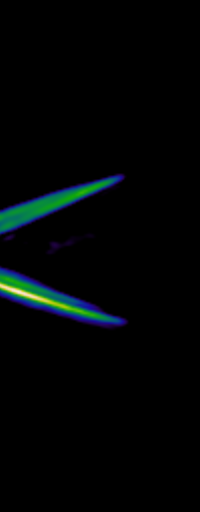
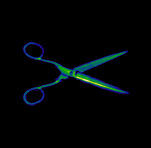
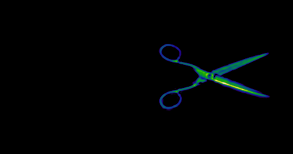
Examples for different objectLengthX values:
distanceZToDeepestLayerOfInterest#
Sets the distance in z-direction from the RadarImager to the deepest layer of interest in the object.
- Keep this distance as small as possible for maximum resolution.
- Use it to cut off multi-reflection effects from the background by limiting the selectable depth range.
Applies after new measurement
Changing this parameter requires a new measurement (the object must pass again), because it changes the depth range and therefore the generated image stack.
| Property | Value |
|---|---|
| type | Real |
| Value (default) | 300 |
| unit | mm |
| minInclusive | 100 |
| maxInclusive | 500 |
offsetDistanceX#
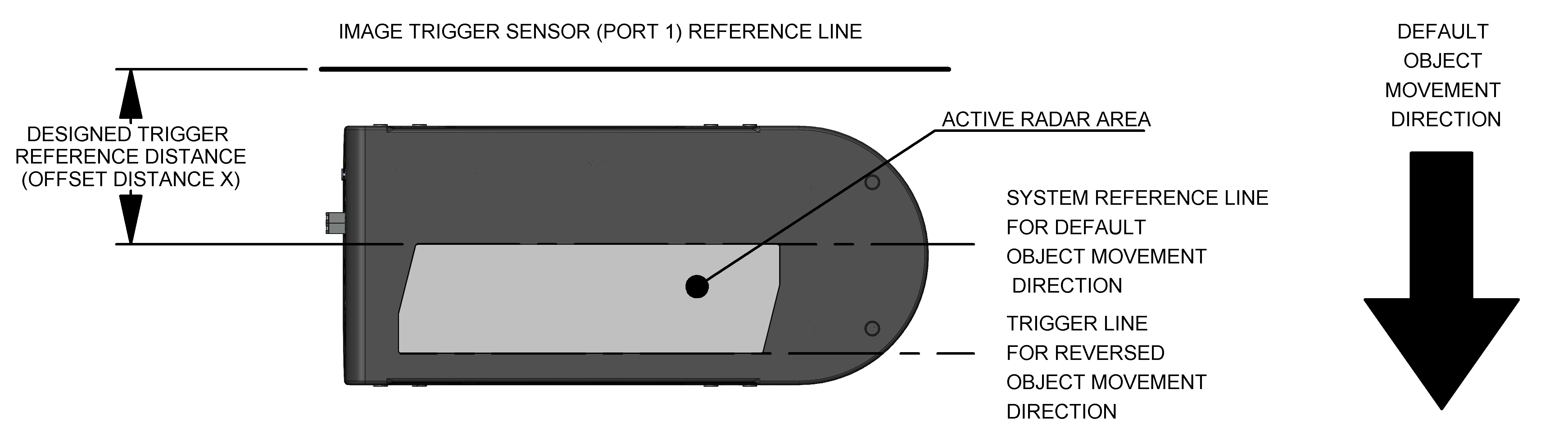
Sets a software trigger delay by defining the distance between the system reference line and the external image trigger sensor along x. This helps capturing the object centered in the image.
Constraint
offsetDistanceX < objectLengthX
| Property | Value |
|---|---|
| type | Real |
| Value (default) | 0 |
| unit | mm |
| minInclusive | 0 |
| maxExclusive | objectLengthX |
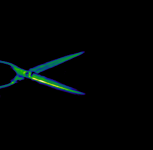
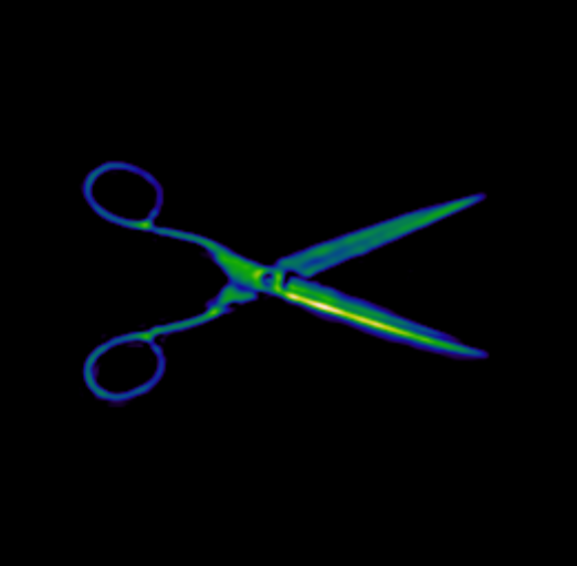
Practical setup tip: start with offsetDistanceX = 0 mm to make sure the object is visible, then increase/decrease it
until the object is centered.
reverseObjectMovementDirectionX#
Reverses the assumed object movement direction along x compared to the default direction shown in the
offsetDistanceX reference figure.
Applies after new measurement
Changing this parameter requires a new measurement (the object must pass again).
| Property | Value |
|---|---|
| type | Option |
| Flag (default) | false |
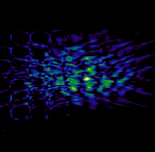
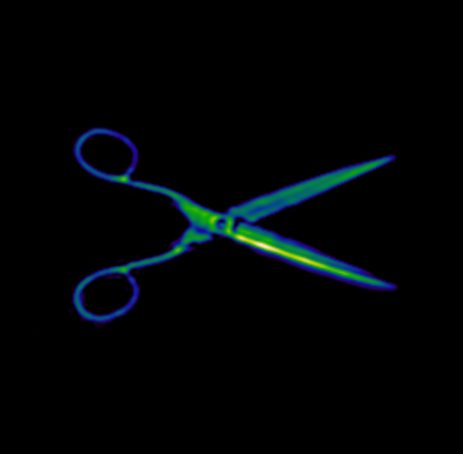
If this is set incorrectly, the measured object won’t be visible in the image:
useExternalTrigger#
Enables the external trigger signal on Trigger Port1 for object detection and image generation. If disabled, external trigger signals are ignored. (Current image won't be overwritten by the next measurement)
| Property | Value |
|---|---|
| type | Option |
| Flag (default) | true |
imageTriggerMode#
Selects how the trigger sensor signal(s) are interpreted.
The used trigger edge (rising/falling) is configured via
imageTriggerRisingEdgeDetection.
There are three modes available:
-
IMAGE_TRIGGER_SIMPLE- Trigger Port1: image trigger sensor
- Trigger Port2: not connected
- Behavior: each configured trigger edge on Port1 generates an image

-
IMAGE_TRIGGER_DIRECTION_SENSITIVE- Trigger Port1: image trigger sensor
- Trigger Port2: additional image trigger sensor
- Use case: suppress triggers for objects moving backwards
- Behavior: Port2 must trigger first and be held → then Port1 triggers → then both release

-
IMAGE_TRIGGER_SIMPLE_WITH_PULSED_SPEED- Trigger Port1: image trigger sensor
- Trigger Port2: pulse generator (e.g. encoder) for live speed measurement
- Behavior: each configured trigger edge on Port1 generates an image; Port2 is used to measure speed using pulses/m
Installation rule
The trigger sensor connected to Port1 is always mounted closer to the RadarImager than the sensor on Port2, independent of the movement direction.
| Property | Value |
|---|---|
| type | Enum |
| Value (default) | IMAGE_TRIGGER_SIMPLE |
| elements | [IMAGE_TRIGGER_SIMPLE, IMAGE_TRIGGER_DIRECTION_SENSITIVE, IMAGE_TRIGGER_SIMPLE_WITH_PULSED_SPEED] |
encoderPulsesPerMeter#
Specifies how many encoder pulses per meter are generated by the belt/object movement. This is used for live speed measurement.
Dependency
Only used if imageTriggerMode is IMAGE_TRIGGER_SIMPLE_WITH_PULSED_SPEED.
| Property | Value |
|---|---|
| type | Real |
| Value (default) | 1000 |
| unit | pulses/m |
| minInclusive | 1000 |
| maxInclusive | 100000 |
encoderUseBothEdges#
Configures whether the encoder signal is evaluated on one edge or on both edges.
- If enabled, rising and falling edges are counted.
- If disabled, only one edge is counted, defined by
imageTriggerRisingEdgeDetection.
encoderPulsesPerMeter always describes the physical encoder pulses per meter.
When encoderUseBothEdges = true, the RadarImager counts two edges per pulse, effectively resulting in
2 × encoderPulsesPerMeter counts per meter.
Example: with encoderPulsesPerMeter = 1000 and encoderUseBothEdges = true, the device evaluates 2000 edges/m.
Dependency
Only used if imageTriggerMode is IMAGE_TRIGGER_SIMPLE_WITH_PULSED_SPEED.
| Property | Value |
|---|---|
| type | Option |
| Flag (default) | false |
imageTriggerRisingEdgeDetection#
Configures whether rising (true) or falling (false) edges are detected for the trigger inputs.
This must match the electrical behavior of the used sensor(s) and wiring (active-high vs active-low).
| Property | Value |
|---|---|
| type | Option |
| Flag (default) | true |
If falling edges are selected, the trigger modes behave as follows:
IMAGE_TRIGGER_SIMPLE

IMAGE_TRIGGER_DIRECTION_SENSITIVE
