Hardware installation#
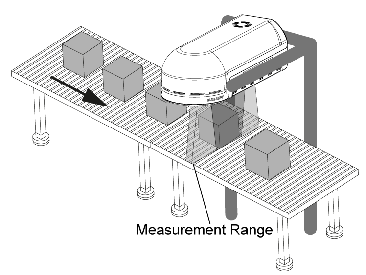
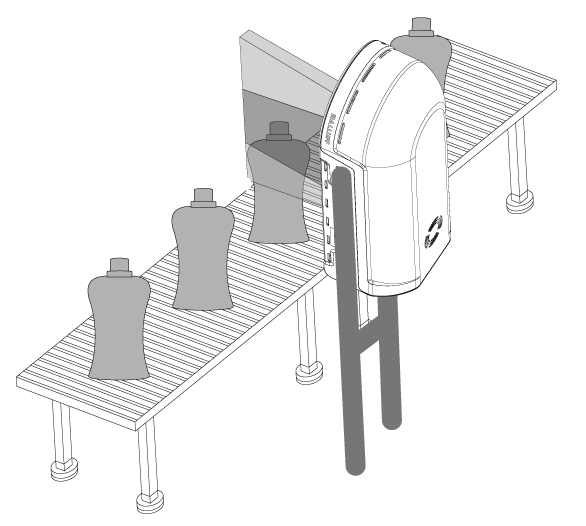
The RadarImager can be mounted in different ways depending on the application. It is designed to be mounted above a moving target object. The RadarImager requires orthogonal alignment, but the entire axis system can be rotated, for example if the conveyor belt is not horizontal.
Typical Orientations#
Acquisition Range#
The RadarImager has an acquisition range of 0.1 m to 0.5 m. Mount the RadarImager so that all layers of interest are within this range.
Since image quality decreases with increasing distance, it is recommended to mount the RadarImager as close as possible to the minimum acquisition distance.
Since image quality is best in the center of the image, mount the RadarImager so that the object is centered.
Alignment#
Ensure the mechanical construction is stable and orthogonal to the target object's movement direction:
- Parallel Alignment: The bottom surface of the RadarImager should be parallel to the movement plane within ±0.3°.
- Orthogonality: The RadarImager axis should be orthogonal to the movement axis within ±0.75°.
- Fine Tuning: Include options for fine-tuning in the mechanical construction.
Initial Alignment#
- Check Level: Use a spirit level or laser alignment tools for the initial alignment. In most cases, this already provides good image quality.
- Optimize: For further optimization strategies and references, refer to the Optimize Image Quality guide.
Trigger Event#
When the target object reaches the radar range, a trigger event must be generated to capture an image. To create a trigger event, connect a trigger sensor (e.g. a light barrier) to Port1 of the RadarImager.
While the RadarImager is active, it continuously acquires measurement data. An external image trigger does not start the radar measurement itself, but defines when a new image is generated from the continuously acquired measurement data. Without a trigger, no new image is generated, even though the system continues measuring.
Depending on your setup, you can choose the direction-sensitive imageTriggerMode
to detect the object's movement direction. To use this feature, a second trigger sensor must be connected to Port2.
Note
The RadarImager will not generate an image without a trigger event!
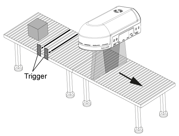
Symbolic trigger position in the figure
The trigger sensor is shown inside the image only to illustrate the geometry.
In the real installation, the trigger sensor on Port1 can be mounted anywhere from the system reference line
up to just below one configured image length objectLengthX upstream.
Mounting rules for the trigger sensor on Port1#
The trigger sensor connected to Port1 always creates the trigger event. It therefore defines when a new image is generated from the continuously recorded measurement data.
For the mounting position of the Port1 trigger sensor, the following rules apply:
- Mount the sensor before the
system reference linein the configured movement direction. - Configure the distance between the trigger sensor and the system reference line with
offsetDistanceX. -
The valid range is:
0 mm ≤ offsetDistanceX < objectLengthXThis means the trigger sensor may be mounted directly at the system reference line, or up to almost one configured image length upstream. 4.
offsetDistanceX = 0 mmis a valid and practical starting point for commissioning. In this case, the RadarImager can still use measurement data recorded before the trigger event to satisfy the angular coverage of the radar field.
Additional mounting rule for direction-sensitive triggering#
If imageTriggerMode is set to IMAGE_TRIGGER_DIRECTION_SENSITIVE,
the second trigger sensor on Port2 must be mounted farther away from the system reference line than the sensor on Port1.
This ensures that a valid trigger sequence is only detected when the object reaches Port2 first and Port1 second.
Sensor order for direction-sensitive mode
The sensor on Port1 is always mounted closer to the RadarImager than the sensor on Port2, independent of the configured movement direction.
If objects follow each other closely, make sure the spacing between consecutive objects is greater than the spacing between the two trigger sensors. Otherwise, two neighboring objects can be misinterpreted as an invalid direction-sensitive trigger sequence.
Note: Speed measurement with external trigger sensors is not supported!
For more information about mounting-related configuration, see Measurement Parameters,
especially offsetDistanceX and imageTriggerMode.
If you want to estimate whether the chosen mounting position, trigger offset, and object speed fit your required installation timing, see the Performance Estimation guide. For a faster interactive check while adjusting these values, use the Performance Estimation Tool.
Object Speed#
For fixed-speed operation, the object speed must be known and configured as
objectSpeedX.
Use a tachometer or another suitable speed measurement tool to determine the object speed to within ±1 mm/s.
If imageTriggerMode is set to
IMAGE_TRIGGER_SIMPLE_WITH_PULSED_SPEED, the RadarImager measures the current speed live via Port2 and
objectSpeedX is ignored.
Live Speed Measurement with Pulses#
Live speed measurement is recommended whenever the conveyor does not run at a perfectly constant speed.
Configure imageTriggerMode to IMAGE_TRIGGER_SIMPLE_WITH_PULSED_SPEED.
In this mode, Port1 remains the image trigger input and Port2 is used as pulse input for live speed measurement.
With live speed measurement, the RadarImager uses the actual movement pulses per meter from Port2 instead of a fixed nominal speed. This allows reliable imaging with variable conveyor speed, startup phases, deceleration phases, and stop-and-go movement. It is even possible to wait through a conveyor standstill without losing the already recorded image progress of the object currently below the RadarImager. As soon as the conveyor moves again and new pulses arrive, image generation continues based on the real movement. This enables 100% conveyor coverage in every operating state, including start-up and temporary standstill.
Typical pulse sources are:
- Encoder on a conveyor roller: the most direct solution if the roller movement represents the real belt movement well.
- Encoder on a measuring wheel: useful if the encoder cannot be mounted directly on the driven roller.
- PLC pulse output: possible when the PLC already knows the movement path and can output 24 V pulses with the same trigger input behavior.
- Other movement-proportional pulse generators: acceptable as long as each pulse corresponds to a defined traveled distance and the output matches the trigger input requirements.
The signal on Port2 must be a 24 V pulse signal and must follow the same electrical specification as the trigger sensors used on the trigger inputs.
The selected edge must match the connected source, so also check
imageTriggerRisingEdgeDetection.
Calculate encoderPulsesPerMeter#
If an encoder is mounted on a conveyor roller with known radius or diameter, the required value for
encoderPulsesPerMeter can be calculated from the roller circumference:
- Circumference:
U = π × d [m] - Pulses per meter:
encoderPulsesPerMeter = encoderPulsesPerRevolution / U [1/m]
By enabling the encoderUseBothEdges option, you can double the number
of detected edges to increase the speed measurement precision. This does not change the value of encoderPulsesPerMeter.
For best accuracy, use the effective roller or measuring-wheel diameter under real operating conditions. In practice, this means checking for slip, compression, gearbox ratios, or mechanically generated PLC pulses that may change the final pulses-per-meter value.