Overview#
The RadarImager is a 3D imaging system that uses radar radiation to generate images of moving targets, for example on a conveyor belt. Because radar operates in the GHz range, many dielectric materials such as plastics, paper, and carton are partially transparent to it. This makes it possible to inspect structures through packaging and to perform localized quality checks that are difficult or impossible with purely optical methods.
However, partial transparency does not mean that packaging has no influence on the measurement. Just as glass affects an optical image even when it is transparent, packaging and target geometry also influence radar propagation and reflection. Understanding these physical effects is important for interpreting RadarImager data correctly and for developing robust evaluation strategies.
This theory section therefore explains the basic imaging principle, the most important resolution limits, and the effects of materials and geometry on the resulting radar image.
How a radar scan works#
A scan is created by continuous relative movement between the RadarImager and the target. Either the target moves underneath the sensor or the RadarImager moves over the target.
Unlike a conventional line-scan camera, the RadarImager does not generate a finished image line by line during acquisition. Instead, a complete scan is required before the 3D image can be reconstructed. This is necessary because the system combines measurements from different positions and viewing angles to recover depth information.
The schematic below illustrates this principle. While the object passes the RadarImager, it is observed continuously along the scan direction. For simplicity, the second dimension is not shown, but in reality the RadarImager contains a line of antennas.
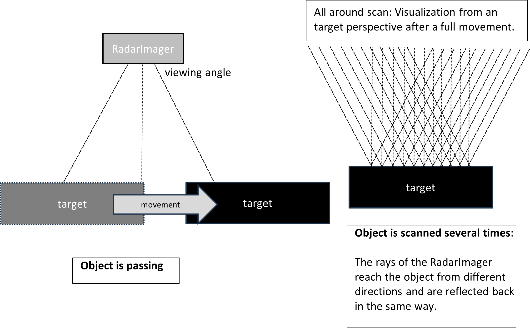
At each moment of the scan, every active radar element observes the target area within an opening angle of roughly 40°. Over the full scan, this provides measurements from many accessible viewing directions. Each measurement corresponds to a radial distance to the target structure.
These data are then reconstructed algorithmically into a 3D grid. The resulting image stack represents reflections at material transitions inside the scanned object or package.
The illustration above shows an idealized case with clear geometry, a single object, one dominant material type, and no disturbing cover layers. Real applications are usually more complex.
The following theory pages describe the most important effects in more detail.