Product description

Construction
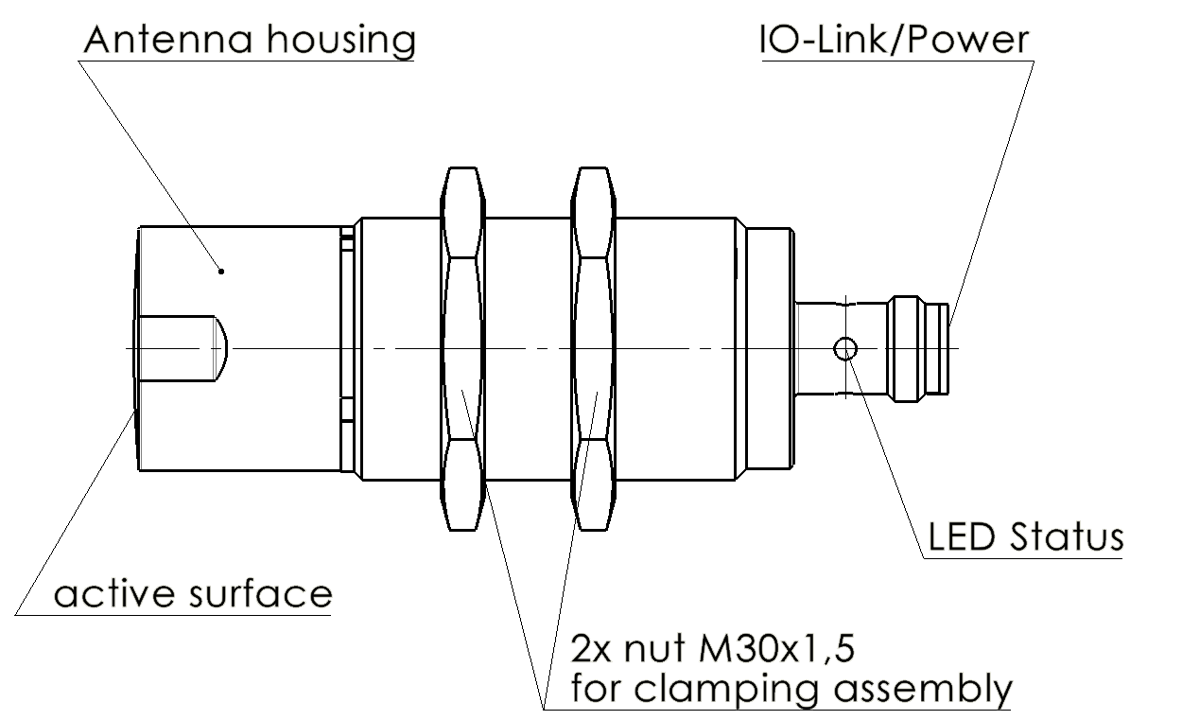
Technical sketch of a sensor with antenna housing, active surface, IO‑Link/power connector, LED status, and two M30×1.5 mounting nuts.

Mechanical labeling of the sensor

Function

The radar sensor BRS S–M30S04–0301–LA2–000S04 is optimized for measurements in industrial close-range applications and offers a range for object detection of up to 15 m. Its robust, cylindrical M30 housing has proven itself in many industrial sectors.

Interfaces and Parameterization:

  • IO-Link: Standardized interface according to IO-Link specification. Allows parameterization of the measurement mode and foreground/background suppression, as well as other parameters.

  • Analog: Additional interface for versatile applications.

Operating principle: The sensor operates using the frequency-modulated continuous wave method (FMCW) in the 122-123 GHz ISM band. It emits a continuous radar signal whose frequency is varied. This enables the sensor to reliably detect the distance to static and moving objects.
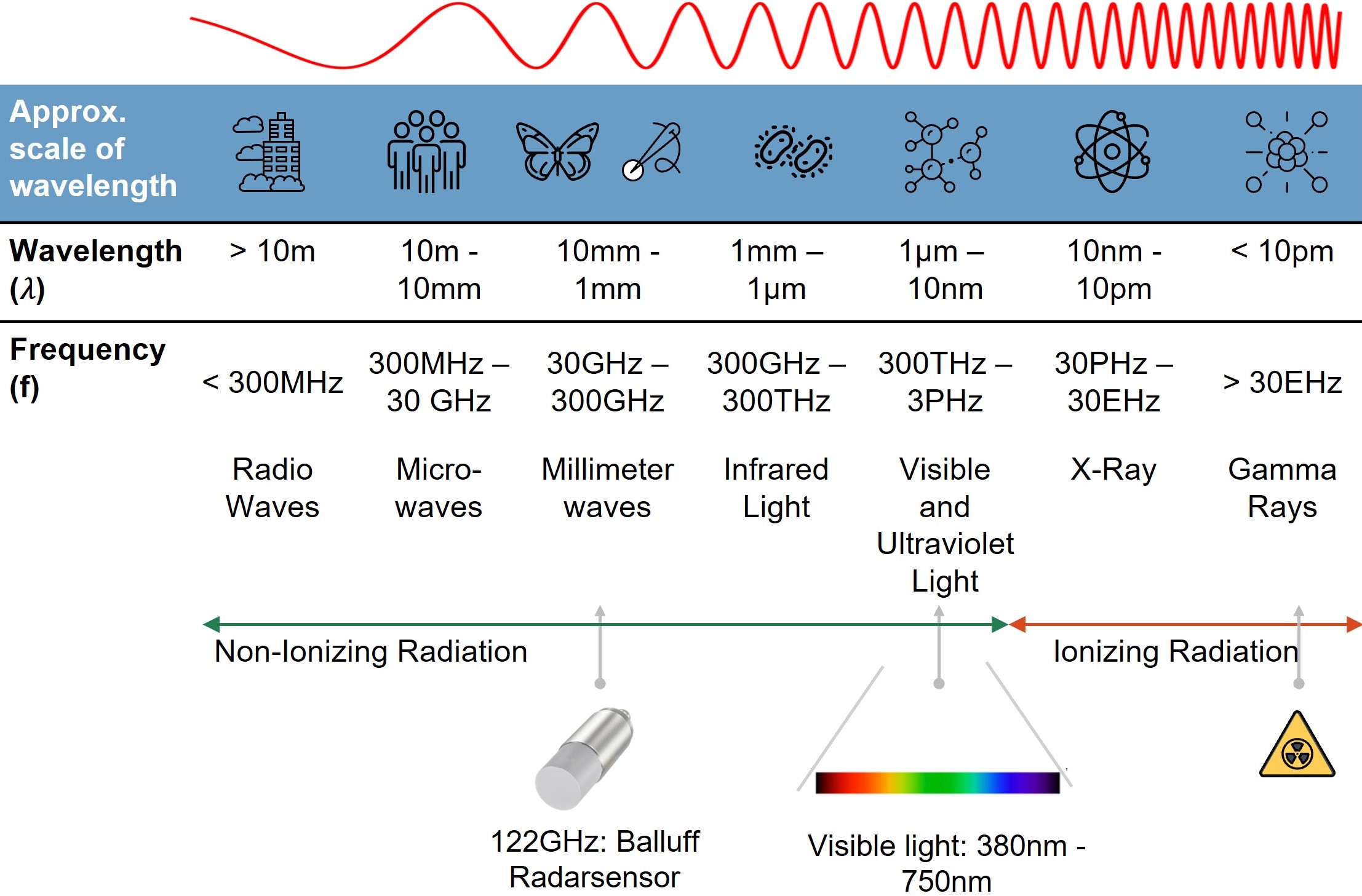
Electromagnetic spectrum diagram with wavelength and frequency ranges, icons for scale, a marker for a 122 GHz radar sensor in the millimeter‑wave band, and an arrow indicating non‑ionizing vs ionizing radiation.

Position of a 122 GHz radar sensor in the electromagnetic spectrum

Performance features:

  • High resolution: Up to 1 mm.

  • High measurement rate: Up to 1 kHz enables the detection of more than 100,000 objects per hour.

  • Low blind zone: Only 300 mm (depending on the target object and environmental conditions).

Typical applications:

  • Distance measurement (e.g., diameter of a film roll).

  • High-speed close-range object detection (e.g., bottles in filling lines).

  • Detection of objects with challenging surfaces (e.g., tires).

Advantages:

  • Measurement of distance and close-range object detection.

  • Reliable and precise measurements in fast applications.

  • Resistant to dust, dirt, moisture, direct light, or darkness.

  • IO-Link interface for service and process data as well as parameterization.

  • Washdown-capable thanks to IP69K.

  • Increased EMC resistance.

  • Proven M30 housing design.

  • Flexible mounting.

Display Elements

LED 1 (Operating State and Communication)

LED 1 (Operating State and Communication)

Name

Signal

Meaning

Failure

Red, static

General error

Communication

Green, alternating with LED off in a ratio of 10:1, 1 s period

IO-Link communication is active.
The device is ready.

Ready

Green, static

The device is ready.

Firmware Update

Magenta, alternating with LED off in a ratio of 9:1, 1 s period

Firmware update is in progress.
The LED indicates update activity.

LED 2 (Indication/Warning/Teach/Device Discovery)

LED 2 (Indication/Warning/Teach/Device Discovery)

Name

Signal

Meaning

Locator

Blue, double blink (2×100 ms on, 100 ms pause), then 600 ms off – 1 s cycle

The function Locator can be activated via a system command to find the device again.

Maintenance required

Blue, static

Perform a factory reset

Short Circuit Pin 2 / Pin 4

Red, flashing, 3 Hz

Short circuit at pin 2 or pin 4

Teach-in

Red, static

The device is currently in teach-in mode.

Overload

Orange, flashing, 3 Hz

Overload on pin 2 / pin 4 has been detected.

Bad Signal Quality

Orange, flashing, 1 Hz

Poor signal quality, the signal quality is below the configured warning threshold.

Out of Specification

Yellow, flashing, 3 Hz

The device is operated outside of specifications. The measurement value is unknown due to an error or outside of the measurement range.

Function Display

Yellow, static

Switching point is active.

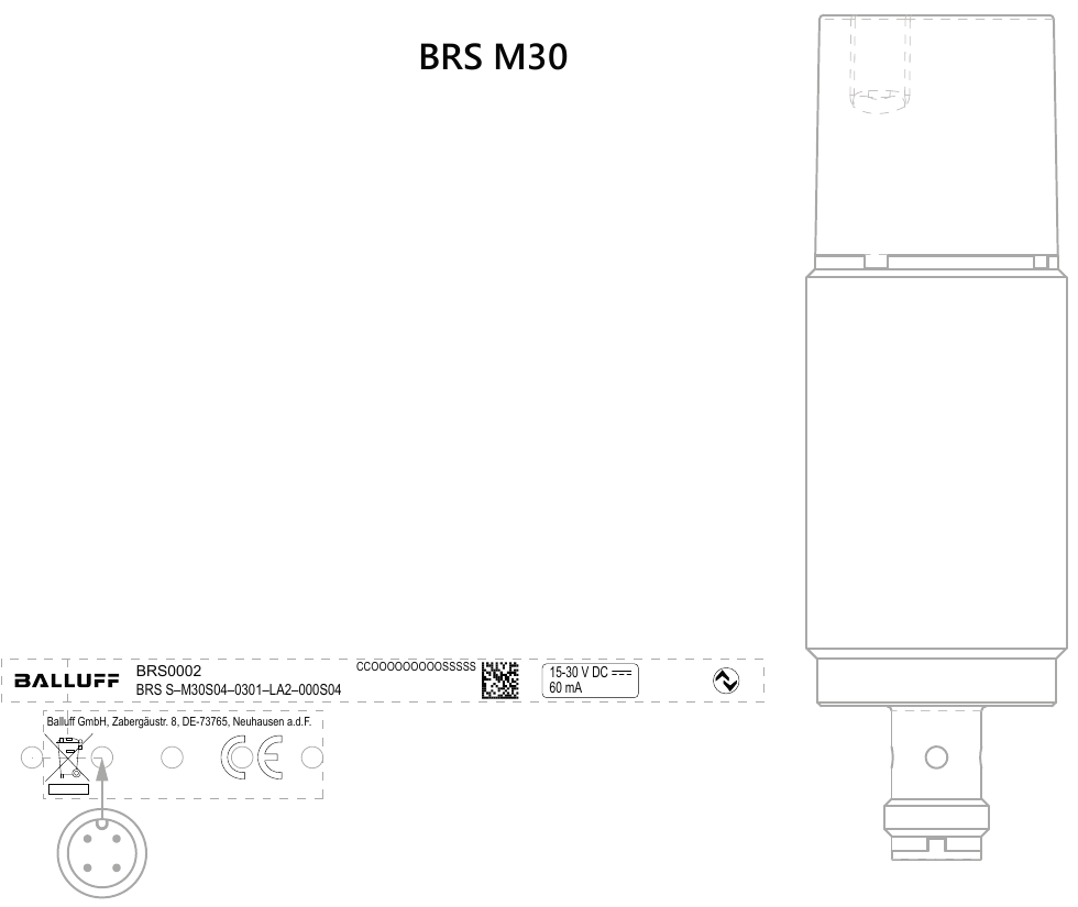
Laser printing

Line drawing of the BRS M30 sensor with nameplate area (product ID, QR code, regulatory marks, 15–30 V DC 60 mA) and M12 connector at the bottom.

Product outline and nameplate layout for the BRS M30 sensor